


Amadeus
 06-30-2015, 03:59 PM
#26

Thread Starter
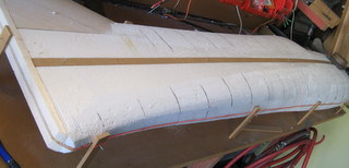
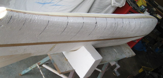
Faceted the bottom of the fuselage. Going to experiment with a dorsal fin as an add on and this will help integrate it into the rest of the fuselage.
Last edited by RodneyFord; 06-30-2015 at 08:22 PM.
 07-02-2015, 01:38 PM
#30
Thread Starter
It is Rohacell 51. A group of us got together and imported a good batch of 800 x 1200 sheets from Clarasonic in Thailand NZ$50 (US$40) a sheet. We got a range of thicknesses 1-3mm in .5mm increments, I am thinking 1mm for this model. Interestingly if you google thermo forming Rohacell there is plenty of info out there. I usually use a heat gun to form the PCV foam we have been using but will try going further and get the Rohacell to form to the full canopy shape.
Rod
07-03-2015, 12:25 AM
#32
Hi Rodney,
An idea might be to keep the plug for thermo-forming.
Any reason why you did not go for the 31 ?? A M\2 of 31 at 1.5mm weighs less than a 1mm M\2 of 51. You can use the 1.5mm in the big flat areas for extra stiffness in the section.
We found the 31 plenty strong enough in compression for all our lay-up purposes and out of the sandwich it is way stiffer than the same thickness honeycomb.
I have never used carbon veil in a mold lay up but I am using it instead of glass for finishing.
It might be worth your while to try ; 0.5oz outside and 0.3oz on the inside on a 10cm X 10cm test piece - I pretty sure it would be great.
However glass on Rohacell looks nice.
Brian
Last edited by serious power; 07-03-2015 at 12:28 AM.
07-03-2015, 12:53 PM
#33
Thread Starter
"Hi Rodney,
An idea might be to keep the plug for thermo-forming."
Yes I thought that too. Although I usually do it into the mold. I might need to get some high temp vaccuum film And heat the foam through that.
"Any reason why you did not go for the 31 ?? A M\2 of 31 at 1.5mm weighs less than a 1mm M\2 of 51. You can use the 1.5mm in the big flat areas for extra stiffness in the section.
We found the 31 plenty strong enough in compression for all our lay-up purposes and out of the sandwich it is way stiffer than the same thickness honeycomb."
Actually I never thought about getting the 31. We were mainly interested in doing the 40% IMAC models with composite wings. I think the 51 is for a better surface finish when pulling full vacuum. You are right about the big flat areas, am thinking about a honeycomb ladder down the fuselage.
"I have never used carbon veil in a mold lay up but I am using it instead of glass for finishing.
It might be worth your while to try ; 0.5oz outside and 0.3oz on the inside on a 10cm X 10cm test piece - I pretty sure it would be great."
I will do some test pieces. It would be interesting to see how the carbon veil handles. The CL guys use it on their wings, which might be worth thinking about. I wonder how it would effect the RF. Mind you I'm flying Jeti with dual path so with the telemetry would probably get it sorted out.
"However glass on Rohacell looks nice."
This is plan A however I have enough 1oz Kevlar if I decided to go that way.
Brian
Probably use lacquer as the gel coat for the weight saving over epoxy undercoat.
I had better see if I can find some finished weights to aim for.
Rod
Last edited by RodneyFord; 07-03-2015 at 01:11 PM.
07-05-2015, 02:45 PM
#35
Thread Starter
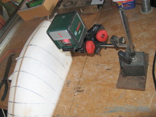
Glued the other stiffener in. The first one was already holding things straight. Here is the laser on a magnetic stand. The laser is also great for marking out rudder cable runs.
07-05-2015, 03:55 PM
#36
Thread Starter
I like the idea of building my own drive system modeled after the Adverrun design. The concept has been around for a while, here is a diagram from 2000 for an air boat drive.

The Brenner and Adverrun systems seem to be running props around 4000 rpm. This will determine the gear ratio given the motor Kv and the battery voltage. Out runner heli motors look to have the right Kv, light weight and reasonable cost.
Example
Kontronic 650-62 Kv 620 so it will be doing a nominal 22940 rpm on 10 cells. so it will need a ratio of 5.735/1 to run the props at 4000 rpm.
I have been looking at gears and belts to see what is required. It looks like 1mod for the gears and GT3 for the belts. A 14 tooth belt pinion is a good number so that 6 teeth are always in contact with the belt so we get a pulley of 80 teeth. Minimum distance between centers is around 47mm. A 14 tooth 80 tooth 1 mod gear drive is 49mm between centers so they look pretty closely matched.
Here is a quick sketch of the basic dimensions to see if it will fit in. Looks OK.
Last edited by RodneyFord; 07-05-2015 at 04:22 PM.
07-08-2015, 05:55 PM
#38
Thread Starter
Masked to the center line then put 2 layers of 200gm glass on one side. This goes down nicely in one piece so the only join is on the hard center line.


07-08-2015, 06:26 PM
#39
Thread Starter
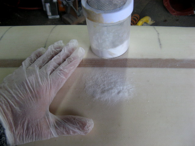
Here is a technique I use when glassing wings. Before the resin goes off spread micro-balloons over the surface and rub in. Fills a lot of the weave and doesn't need sanding.

07-08-2015, 10:19 PM
#40
Thread Starter
Well it looks like the biggest challenge with this drive is juggling all the variables and sourcing the parts. I now know a lot more about timing pulleys and belts. The design gradually comes together. It looks like a 520 kv motor is necessary. I could rewind a motor as I have built quite a few CD rom motors for indoor and have a winding machine, however not too keen on that as I know the difficulties . Looking like I need 1 mod spur gears and 3mm GT2 tooth belt drive with the whole thing made to work with a 80 tooth belt 9mm wide. I'm kind of thinking the rear prop can run at a (slightly) faster speed than the front one.


. Looking like I need 1 mod spur gears and 3mm GT2 tooth belt drive with the whole thing made to work with a 80 tooth belt 9mm wide. I'm kind of thinking the rear prop can run at a (slightly) faster speed than the front one.
07-10-2015, 04:12 PM
#41
Thread Starter
Trimed the first side down the center line, re-masked and got the other side glassed. It will get a bit samey for a while as I go through the surfacing procedure but I will keep posting anyway.
07-13-2015, 08:55 PM
#46
Thread Starter
Well I can get the the system meshing with a 16 tooth/72 tooth belt and a 17 tooth pinion 80 tooth spur gear. This gives 4.75:1 on the front prop and 4.5:1 on the rear prop. This would suit a 520kv motor. The fly in the ointment is that there are only 4 teeth of the belt meshing with the 16 tooth pulley, 6 is regarded as a minimum. Perhaps that would be a good reason for using a 15mm wide belt rather than 9mm. I will see if things can be improved by re gearing for a 450kv motor, 3.6:1 should give a good belt mesh.
Many thanks to Brenner for his work and posting it here. As well as the correlation of Kv to prop rpm he has shown a correlation between KV and gear ratio. Most useful.
Many thanks to Brenner for his work and posting it here. As well as the correlation of Kv to prop rpm he has shown a correlation between KV and gear ratio. Most useful.
Last edited by RodneyFord; 07-13-2015 at 09:15 PM.
07-17-2015, 08:08 PM
#47
Thread Starter
Sanded off the micro balloons It is looking OK. Put on some more but only where necessary. Hopefully will get a dark colour on tomorrow so I can get a good look at it.


07-18-2015, 05:15 PM
#48
Thread Starter
Got a good mesh with 19-72 3Gt timing belt and 20-76 tooth Mod 1 spur gear (0.1mm difference) . This is possible due to the 95mm diameter spinner. Ordered a Scorpion HK 4035 450 Kv motor. Have a set of Mod1 gear cutters coming from China. 3GT belt and pulleys are from BandB in the USA. Here is a more complete preliminary drawing.

07-18-2015, 06:16 PM
#49
Thread Starter
Took a bit of work to sand the green epoxy/microballoon mix off. Got a coat of epoxy undercoat on. Not too bad a surface, I will start in with the polyester filler now. This is pretty fast to work with.
