


CARF Rebel MAX - Build Thread
 11-01-2021, 04:25 AM
#26

Thread Starter
My Feedback: (1)

Kenrico,
I definitely agree with Dave. While completely incasing the pushrod in a carbon tube or brass tube would indeed be stronger, I believe the amount of force that would be required to bow that small portion of exposed rod is greater than the plane will ever experience. I may go back after I finish and put a full-length piece on all of them if for no other reason than uniformness and aesthetics but, I'm trying to also build it as it comes (unless there's something glaringly wrong which I doubt) so that those that don't have a lot of building experience can have some sort of "manual" to follow. Definitely, thank you for bringing that up, however. I'm sure we all do appreciate it as this thread ages.
I definitely agree with Dave. While completely incasing the pushrod in a carbon tube or brass tube would indeed be stronger, I believe the amount of force that would be required to bow that small portion of exposed rod is greater than the plane will ever experience. I may go back after I finish and put a full-length piece on all of them if for no other reason than uniformness and aesthetics but, I'm trying to also build it as it comes (unless there's something glaringly wrong which I doubt) so that those that don't have a lot of building experience can have some sort of "manual" to follow. Definitely, thank you for bringing that up, however. I'm sure we all do appreciate it as this thread ages.
 11-01-2021, 07:05 AM
#27

Scott,
yes I am going with a Swiwin 300 in mine as the loss where I fly is about 18-19%, which means I am running about a 240 at the end of the day.... in the 300 I like an 8mm vent and run from tank to UAT.... just wondering if that might be overkill or not was all.
yes I am going with a Swiwin 300 in mine as the loss where I fly is about 18-19%, which means I am running about a 240 at the end of the day.... in the 300 I like an 8mm vent and run from tank to UAT.... just wondering if that might be overkill or not was all.
11-01-2021, 07:28 AM
#28
Thread Starter
My Feedback: (1)
Scott,
yes I am going with a Swiwin 300 in mine as the loss where I fly is about 18-19%, which means I am running about a 240 at the end of the day.... in the 300 I like an 8mm vent and run from tank to UAT.... just wondering if that might be overkill or not was all.
yes I am going with a Swiwin 300 in mine as the loss where I fly is about 18-19%, which means I am running about a 240 at the end of the day.... in the 300 I like an 8mm vent and run from tank to UAT.... just wondering if that might be overkill or not was all.
I'd like to run 8mm to the vent so that there is no possibility for vacuum on the tank. Yes, it's overkill but it certainly doesn't hurt anything and more air from external vent to tank does not hurt our weight.

Last edited by smcharg; 11-01-2021 at 07:36 AM.
11-01-2021, 02:35 PM
#29

Scott,
yes I am going with a Swiwin 300 in mine as the loss where I fly is about 18-19%, which means I am running about a 240 at the end of the day.... in the 300 I like an 8mm vent and run from tank to UAT.... just wondering if that might be overkill or not was all.
yes I am going with a Swiwin 300 in mine as the loss where I fly is about 18-19%, which means I am running about a 240 at the end of the day.... in the 300 I like an 8mm vent and run from tank to UAT.... just wondering if that might be overkill or not was all.
Last edited by Ruizmilton; 11-01-2021 at 09:53 PM.
11-01-2021, 02:49 PM
#30
As stated by others, the plane does fly very well with a lot less power than a 300, I understand the thrust loss concern, I�m at sea level, yet at 90 degrees F 95% of the year, I had a 300 in mine and it was very difficult to land because of residual thrust as the Max lands very slowly, plus the extra needed weight in the nose to counter the engine weight. Well built and thought out the plane�s weight could be at 38-42 lbs dry, with a 300 you are at very close to 2/1 ratio. As recommended by others who fly with a 210, I replaced the 300 with a 200 I had on hand, unless I want to be really fast, I do not need more. With your thrust loss, a 230-260 should suffice and be fairly fast as well, plus lighter weigth!
The following users liked this post:
Skunkwrks (11-02-2021)
11-01-2021, 05:44 PM
#31
My Feedback: (20)
In all my 300N class turbines I always run 6mm or 1/4" ID (8mm OD poly or 3/8" OD Tygon) plumbing from the vent to tank, clunk to air trap, and to pump. I use flexible Viton inside the tanks. I step the large tubing down just prior to the pump if necessary. Then what ever poly tubing the turbine calls for from pump to turbine. I have never had any air bubbles or cavitation issues at high power and I'm sure my PW is lower because of less internal suction pressure in the plumbing. Lots of folks tell me I'm nuts and it's overkill but I have yet to have a flameout on a 300N class turbine. If the larger fittings are not installed on the tanks I cut them out and put in the 1/4" ID fittings and clunks from Jet Tech. A little more work but it works!
Gary
Gary
Last edited by Viper1GJ; 11-01-2021 at 05:57 PM.
The following users liked this post:
AEROSHELDON (11-02-2021)
11-02-2021, 08:13 AM
#33
Thread Starter
My Feedback: (1)
Since I'm currently installing the Electron retracts (pictures coming soon) and running the wires, I thought I would pose a question to the experts that already have the Max and Dave Wilshere .
While assembling the Electron gear, I started looking at the wheel hubs/brake system and thought about wheel direction. If you place it to where the brake is facing the inside and the "rim" is to the outside when extended, this means the strut is in the wing first and the wheel assembly is on bottom (facing out) when retracted. If I want the wheel to retract into the wing first, then the "rim" is to inside when extended. I'm sure this is personal preference and I do want the "rim" (pretty side) showing outward but I am wondering if there is a "wrong" way to do this before .... I do this.
In the video Sheldon posted earlier from Elad Fish, he has his "rim" mounted "inward" and also in the CARF video of Andreas flying the Max. I want mine the opposite way. So, is there a right or a wrong way for the wheels to face (aside from aesthetically)?
Last edited by smcharg; 11-02-2021 at 08:49 AM.
11-02-2021, 09:10 AM
#34

I have the Pro with the same gear, but I think if you place the rim on the out side like you want it might not fully retract in to the wing. you would have to try it maybe the Max is a little different .
The following users liked this post:
smcharg (11-02-2021)
11-02-2021, 11:45 AM
#35
Thread Starter
My Feedback: (1)
I'm pretty sure I found my answer. Kenrico said it and that makes sense as the wheel would stick out of the well if I did it the way I thought I wanted to. I also found a picture of how Electron suggests to do it as well on the jetstreamuk website. So, I'll do it this way and live with the "bling" facing the inside.
I just ordered a manual gear extender for the Electron gear as well. I haven't put the gear together yet but it's quite obvious by the picture that the wheel would, indeed, stick out if it was reversed.
I just ordered a manual gear extender for the Electron gear as well. I haven't put the gear together yet but it's quite obvious by the picture that the wheel would, indeed, stick out if it was reversed.
11-02-2021, 11:58 AM
#37
Thread Starter
My Feedback: (1)
I've been looking for the manual gear controller but they've been out of stock lately. I looked today and they're finally back. AEROSHELDON , is it smart to put some goop or something on the brake +/- connection or is the click to connect enough? If you put a compound on the connection, what are you using?
Last edited by smcharg; 11-02-2021 at 12:04 PM.
The following users liked this post:
smcharg (11-02-2021)
11-02-2021, 03:43 PM
#39
Manual gear controller is a must. I got mine from Aeropanda. I installed the gears without it and just trying to eye ball it and had to redo one of them as they would bind up on the well while opening.
11-02-2021, 05:41 PM
#40
My Feedback: (20)
Here is where I learned my techniques. Lots of good info here especially the section on avoiding restrictions.
https://www.ultimate-jets.net/blogs/...considerations
Gary
https://www.ultimate-jets.net/blogs/...considerations
Gary
11-03-2021, 04:29 AM
#41
My Feedback: (1)
I'm pretty sure I found my answer. Kenrico said it and that makes sense as the wheel would stick out of the well if I did it the way I thought I wanted to. I also found a picture of how Electron suggests to do it as well on the jetstreamuk website. So, I'll do it this way and live with the "bling" facing the inside.
I just ordered a manual gear extender for the Electron gear as well. I haven't put the gear together yet but it's quite obvious by the picture that the wheel would, indeed, stick out if it was reversed.
I just ordered a manual gear extender for the Electron gear as well. I haven't put the gear together yet but it's quite obvious by the picture that the wheel would, indeed, stick out if it was reversed.
11-03-2021, 12:57 PM
#42
I have a customer who swapped the legs/wheels on his 2m Rebel, the wheels just sit below the wing skin when retracted. Although that’s not how it’s designed, there is no real right or wrong with a sports jet. He liked the idea of wider wheel track and also if his gear jammed up, landing on the slightly proud wheels would protect the wing skin.
Most important thing on leg installation is flats on the pins! People miss that and the set screws will not grip the rock hard pins Electron supply.
Most important thing on leg installation is flats on the pins! People miss that and the set screws will not grip the rock hard pins Electron supply.
The following users liked this post:
smcharg (11-03-2021)
11-15-2021, 07:58 AM
#43
Thread Starter
My Feedback: (1)
Hi guys,
Told you I was a little slow. Actually, I'm not this slow but, sometimes I have to travel as I do some contract work for the military flying UAV's. Last week was one of those weeks where I was gone.
I have now completed the wings. I've decided to wait until I finish the rest of the Max before putting on the AMP connectors to tie the wing electronics to the fuselage so, when I say completed the wings, I mean I've completed the installation of all the components. While the left wing was aligned very well for the aileron servo and pushrod to the left aileron control horn, the right wing was off just a little. It seems as if the mounting rib wasn't placed exactly the same as the left wing at the factory. It's not off by much, maybe 3mm but it is enough where I wound up having to use a Dremel to give some clearance for the servo arm. Not a huge deal but the alignment isn't as good. Now, it's not so far off that I'm worried about it because of the ball link connector but it is enough for me to note it here and will keep in mind once I start setting throws and aileron differential. It is possible to put a spacer between the rib and the servo which I may go back and do if I see any weirdness but, as hard as it is to get anything in those bays to tighten simple servo screws, I'm going to wait and see when I set throws.
So, where did we leave off....ah yes! I was fixing to install the main retracts. This part is a piece of cake! If you purchase the Electron ER50evo retracts from CARF, you get the proper struts that are for this aircraft. As most know, the gear are exactly the same for both the PRO and the Max. The holes in the pre-mounted landing gear blocks to hold the retracts are pre-drilled. All you have to do is insert the included blind nut/T-nuts in from the bottom and then bolt in the supplied bolts and washers. Make sure to use Locktite here as well (Blue). Everything was well-aligned which is awesome. I did mix up some 30-minute epoxy and thin with Acetone and brushed that mixture onto the gear blocks first to give it some added strength. I don't have a lot of experience with retracts, well, at least with these kind. My last "installation" of electric retracts was back in the early 90's in pattern ships that still used a 180 degree servo to drive them. I did have a set of JP's in my T-1 but I also had the factory install them and they worked perfectly so I didn't pay much attention. As far as these Electrons go, man, they are fantastic! I don't think you could get any simpler in the assembly and adjustment process. First, as I noted previously, I did buy the Electron manual controller. As others have stated, this is the way to go to set up gear. With the manual gear controller, you simply hold down the "Deploy" button or the "Retract" button to actuate each individual gear. When you release the button, it stops mid-travel (or wherever the gear is in transit when you release the button). What's nice about this is it gives you the ability to check and make sure everything is lined up and it won't hit anything. Additionally, you have to have the gear deployed (read extended) in order to access the grub screws that hold the strut into the unit and, of course, the gear come retracted in the box. Now, you could do this with the GS-200 controller as well but for $30, that manual controller is worth it's weight in gold. Reminder - NEVER hook up a battery directly to the gear. ALWAYS use a controller.
To install the struts, simply remove the 4 grub screws (already in the unit) and apply Locktite to them. Now, I've noticed that some folks have said to make sure to line up the grub screws with the flat spots on the pin that is on the struts. This, of course, makes sense so that the grub screws have something to "bite" into. Let me say that the pins have no flat spots anywhere. I contacted a couple of friends that have these same gear and they confirmed these "flat spots" do not exist (at least on the ER50evo's). Actually, this also make sense because, if the flat spots were there, there would be no way to adjust toe-in/toe-out in the wheels. Anyways, I guess I could be wrong about these flat spots but I could have sworn people were talking about them. I can tell you, there are no flat spots anywhere on the ER50evo gear in relation to the grub screws.
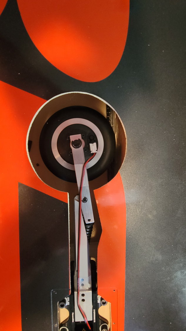
I learned a little trick from a friend and that is to put Locktite on the pin that inserts into the unit. Just smear a little bit on the entire pin. What this does is give the grub screw a little something to "bite" into and I think will work perfectly. So, all that to say, put Locktite on the grub screws, smear a little onto the pin and tighten them up. I did install the pre-assembled axle/brake assembly/wheel assembly onto the strut using the provided C-clip (so freaking easy) before tightening down the grub screws to make sure the wheel was running true. I will revisit this when I finally get the plane completely put together and on it's gear. The only thing to make sure of when putting the axle and assembly on to the strut is the direction of the brake connection. The strut will actually fit perfectly between the brake assembly screw heads to "lock" it in place. See pictures below.
The next thing was to make sure everything was lined up such that the wheel would not touch the skin of the plane while retracting or extending. This is where that manual controller was so nice. I could slowly approach the skin of the plane while actuating the retract. On mine, I found that the wheel would just scrape the front part of the wheel well. Not enough to cause any damage but enough where the wheel was not centered in the well. Not a problem! On the back side of the strut is another grub screw that allows you to adjust the bottom portion of the strut and easily center the wheel in the well. Again, simply remove the screw, apply Locktite to it, put it back in and turn it to adjust the wheel and center it in the well.
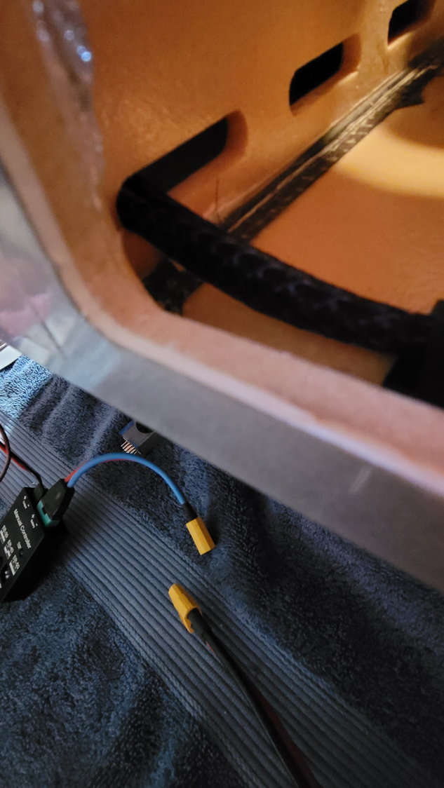
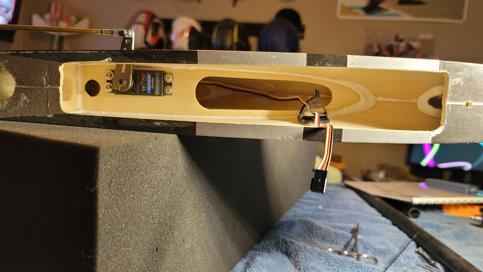
One last thing to note: AEROSHELDON shared a YouTube video by Elad Fish and his Rebel Max. I've watched all of his Max videos a few times over (in fact, I think I've watched every Rebel Max and Pro video on YouTube) and have been following him since before I even started this thread. He's one of the reasons I decided on the KingTech K235G4+ as well. Anyways, I watched that video Sheldon posted....again....paying attention to where he had his AMP connector placed in relation to the wing tube. As I showed in my previous posts, I was bringing all of my cables out through the larger opening in the wing where the retracts were. In the fuse, there are no holes aside from the spar and locating pins. The more I looked at this, the less I liked bringing them out here. Even though I have cable tie downs and there's very little chance of the retracts interfering, you have to always look at the possibilities and not the probabilities. With that being said, I decided to reroute my wiring to the front of the wing (or at least foward of the wing spar tube). The aileron servo and flap servo still use what I showed you before but I continued to pull those through to the front of the wing. I also rerouted the gear cables and brake cables from the location of the retracts to the front of the wing. I think this is a better idea and is what Elad did as well. This allows me to mark the location of this new hole (already there from CARF) on to the wing fillet on the fuse, cut a hole and fasten the AMP connector into the fuse. I'll leave the other side of the AMP connector "loose" in the wing which will allow me to connect them on assembly. There's nothing in that bay of the wings so any "service loop" of wire will be located there and I don't have to worry about anything catching these wires.
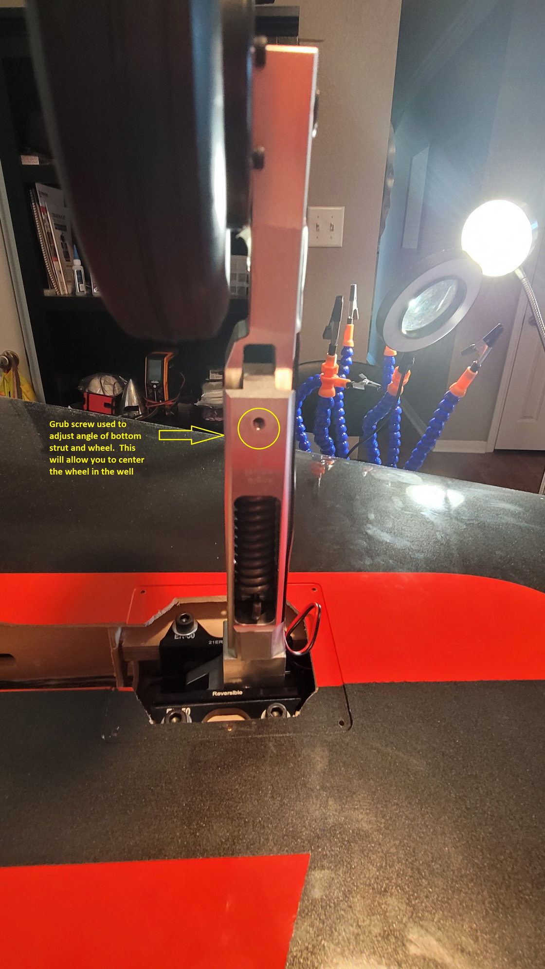
This is the grub screw to adjust the center of the wheel in the well.
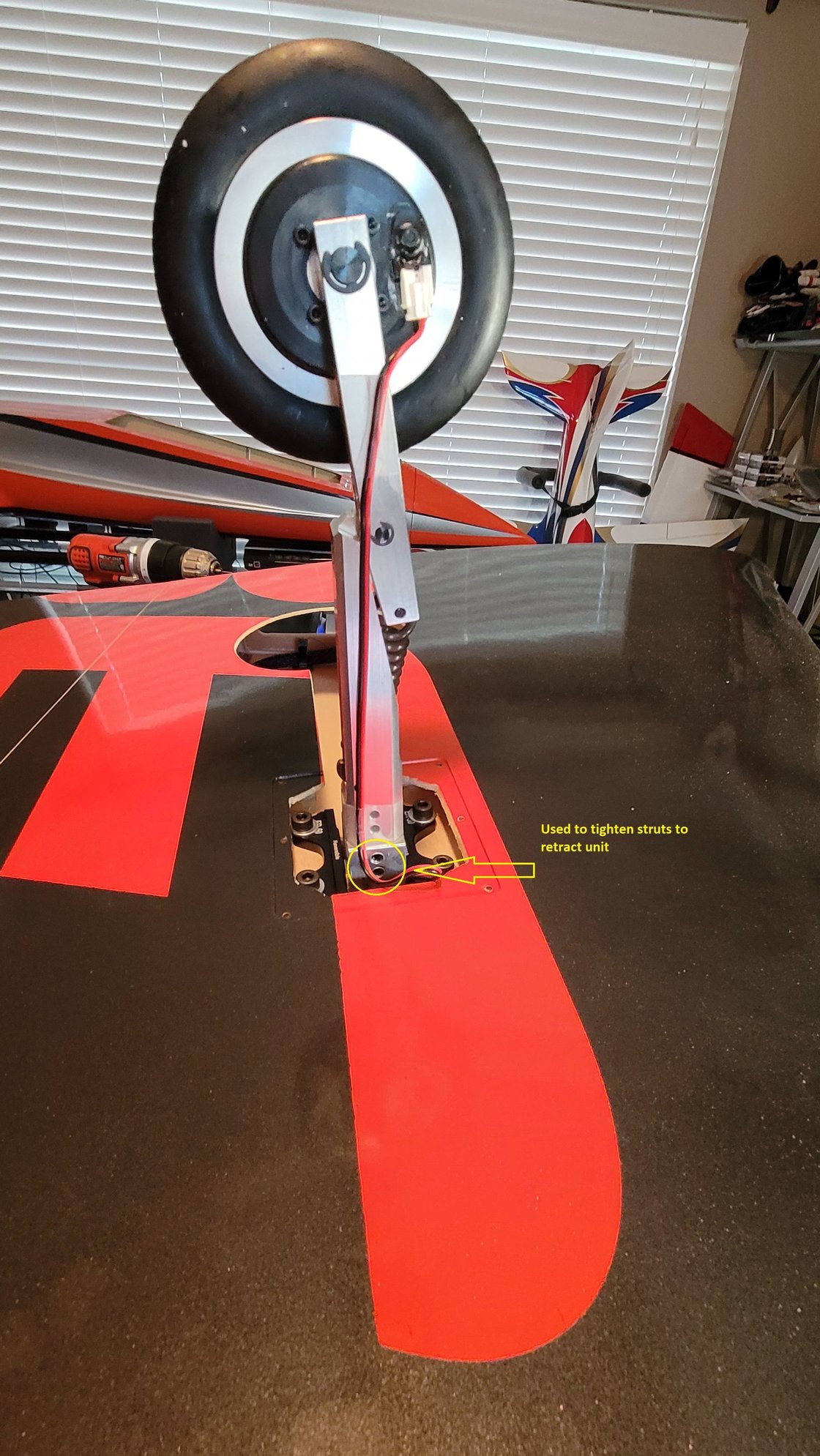
2 of 4 grub screw locations that hold the strut in.
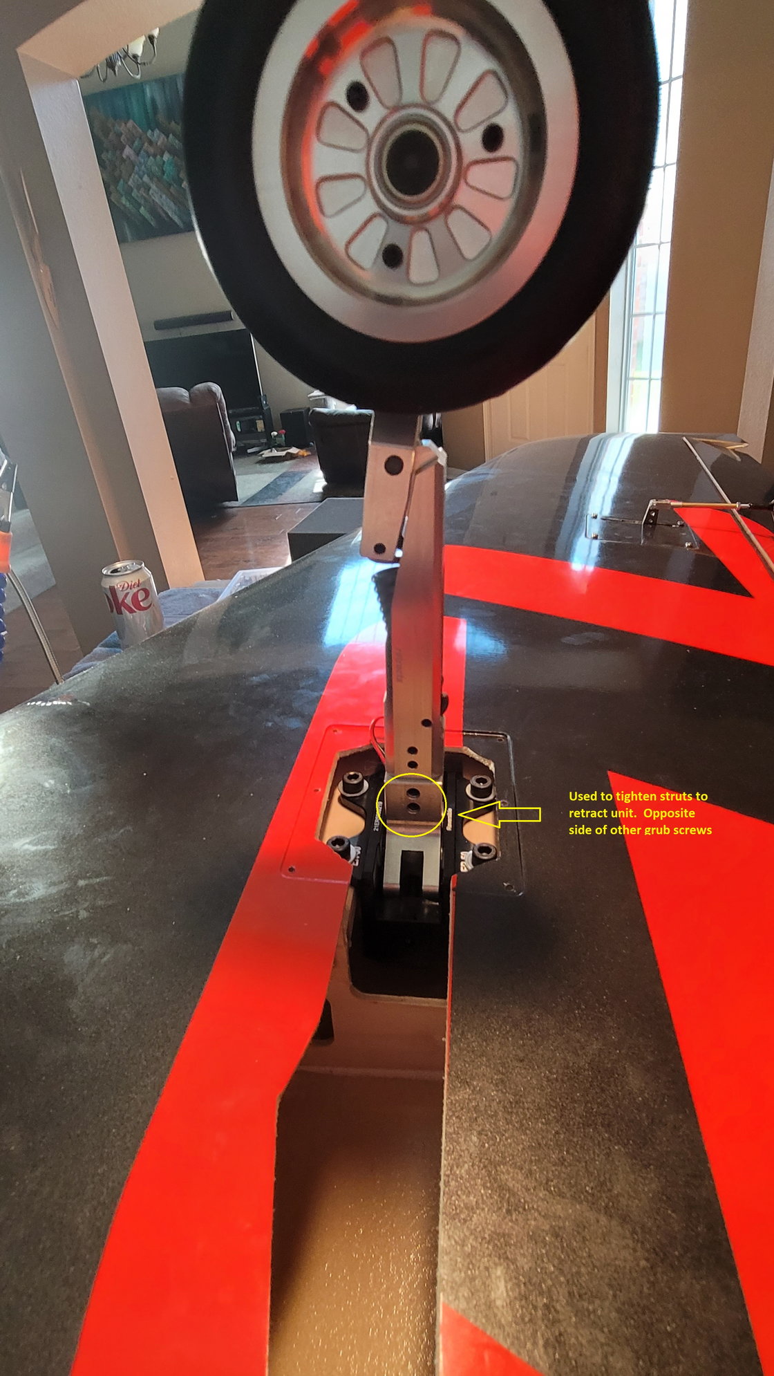
The other 2 of 4 grub screw locations that hold the strut in. These are only accessible with the gear extended.
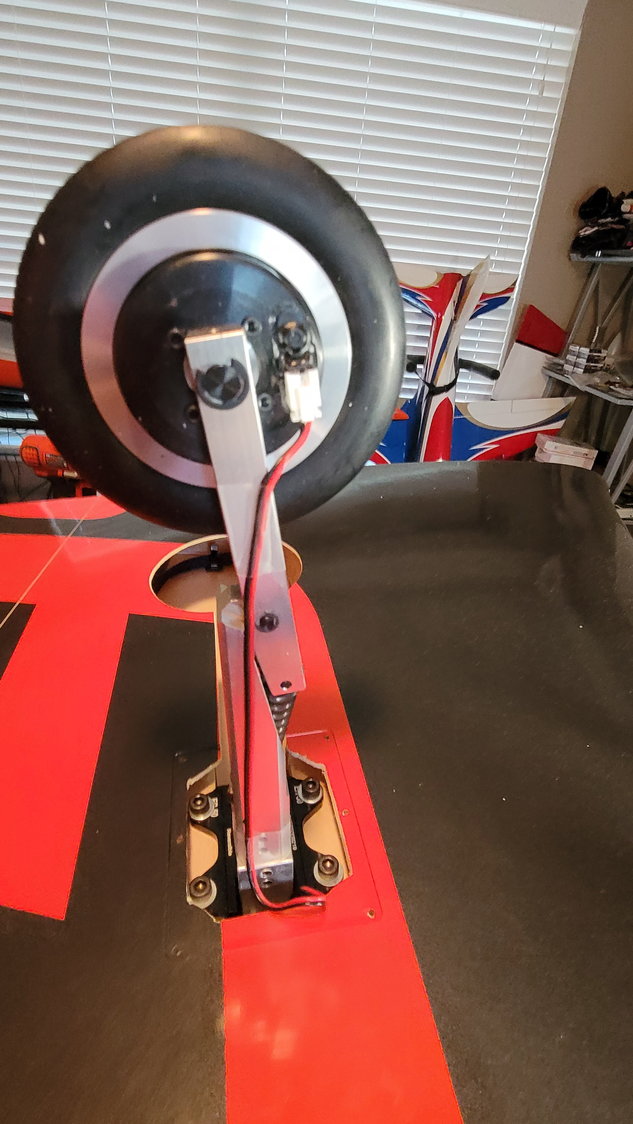
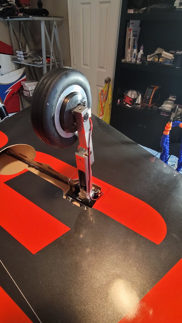
Note the placement of the strut in between the screw heads of the wheel assembly. Make sure the brake connector is pointed the way you want. The C-clip is the only thing holding the entire axle and assembly in the strut. You can also see how I decided to hold the brake wire onto the strut. I use 3M Blenderm medical tape. It is the best tape I have ever used and will not come off until you take it off but doesn't leave residue after the fact.
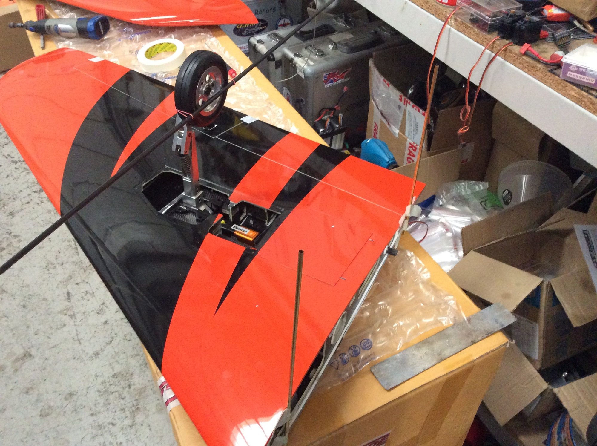
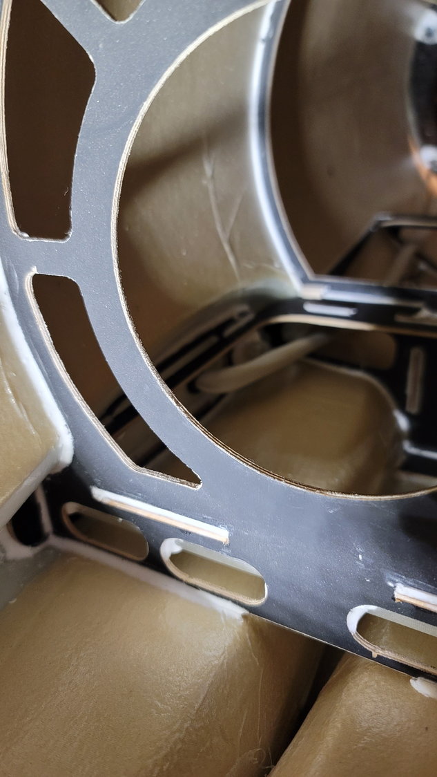
Gear from Electron and ordered through CARF fit perfectly and the wing cut outs required no adjustment for the struts.
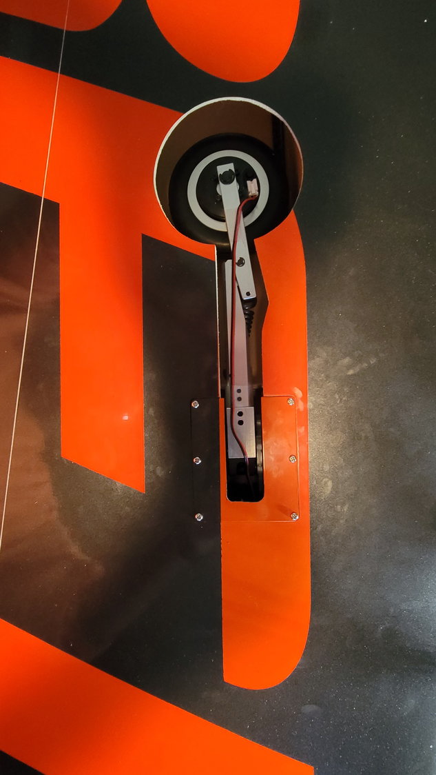
Final assembly with gear plate cover installed
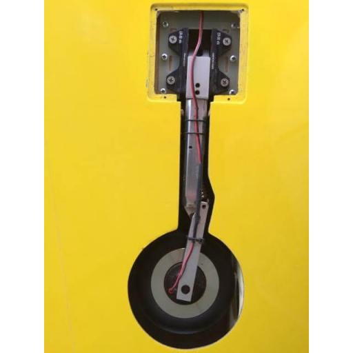
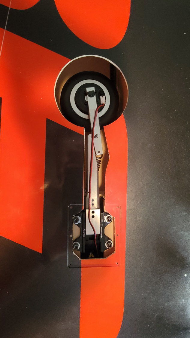
Perfectly centered with clearance all around
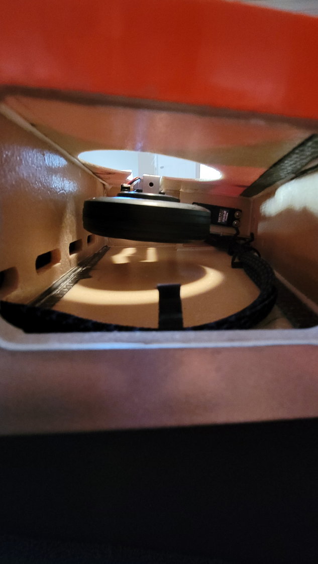
Retracted wheel doesn't even come close to the top of the wing.
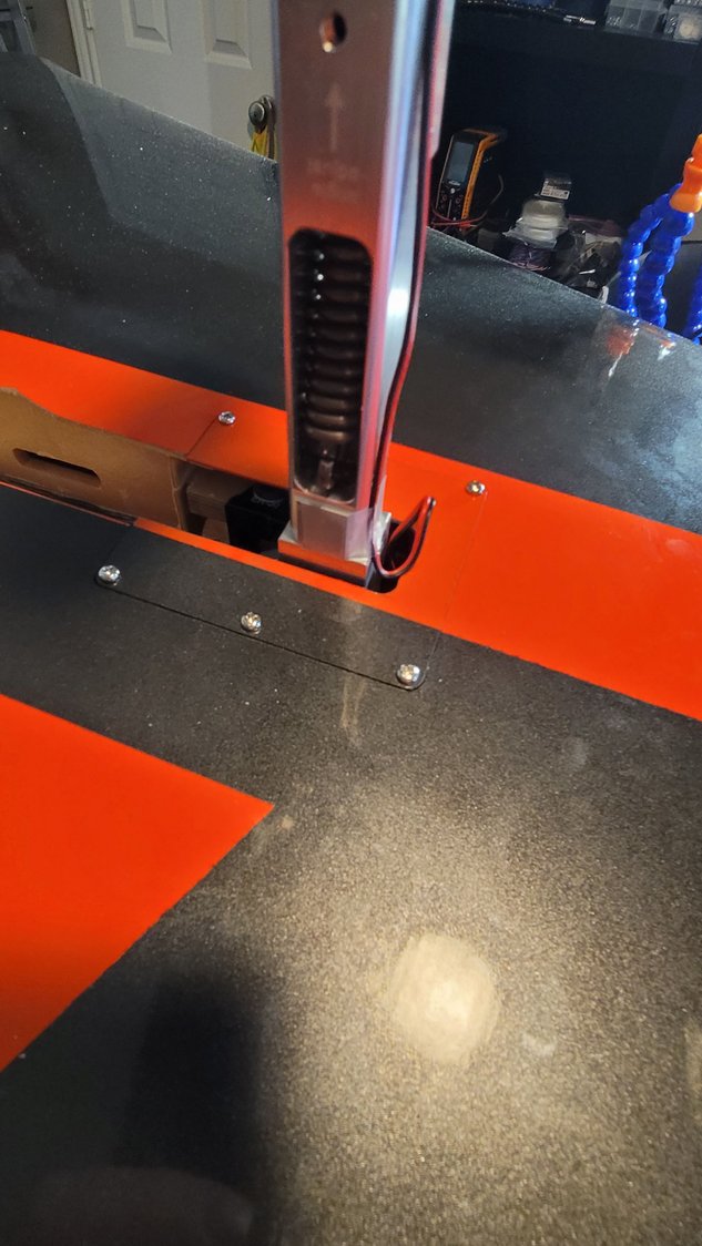
Retract plate cover installed with 6 provided screws. Holes are pre-drilled in the cover so you just have to transfer those holes to the plate, itself. Make sure to run some CA into the holes and let it dry once you've completed them. Make sure to leave enough slack in your brake lines for retraction of the gear!
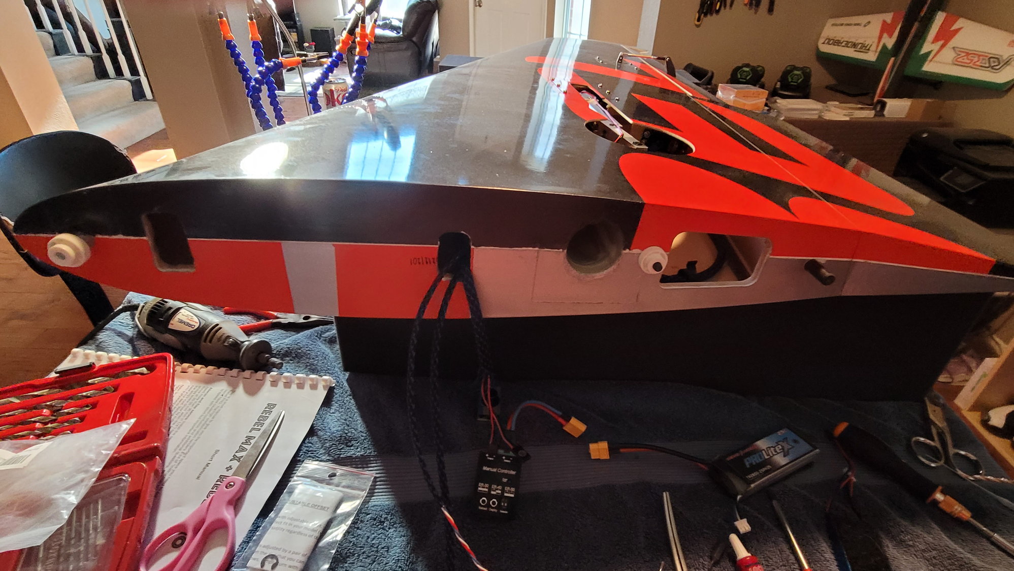
This bay, where the wires come out now, is empty and is separated from the retract bay by sheer web. See next picture(s).
Note that the gear and brake lines go into the wing while the servo bundles are still routed as I showed in an earlier post.
This is the sheer web/spar between the bay I have the wires running to and the retract well.
Told you I was a little slow. Actually, I'm not this slow but, sometimes I have to travel as I do some contract work for the military flying UAV's. Last week was one of those weeks where I was gone.
I have now completed the wings. I've decided to wait until I finish the rest of the Max before putting on the AMP connectors to tie the wing electronics to the fuselage so, when I say completed the wings, I mean I've completed the installation of all the components. While the left wing was aligned very well for the aileron servo and pushrod to the left aileron control horn, the right wing was off just a little. It seems as if the mounting rib wasn't placed exactly the same as the left wing at the factory. It's not off by much, maybe 3mm but it is enough where I wound up having to use a Dremel to give some clearance for the servo arm. Not a huge deal but the alignment isn't as good. Now, it's not so far off that I'm worried about it because of the ball link connector but it is enough for me to note it here and will keep in mind once I start setting throws and aileron differential. It is possible to put a spacer between the rib and the servo which I may go back and do if I see any weirdness but, as hard as it is to get anything in those bays to tighten simple servo screws, I'm going to wait and see when I set throws.
So, where did we leave off....ah yes! I was fixing to install the main retracts. This part is a piece of cake! If you purchase the Electron ER50evo retracts from CARF, you get the proper struts that are for this aircraft. As most know, the gear are exactly the same for both the PRO and the Max. The holes in the pre-mounted landing gear blocks to hold the retracts are pre-drilled. All you have to do is insert the included blind nut/T-nuts in from the bottom and then bolt in the supplied bolts and washers. Make sure to use Locktite here as well (Blue). Everything was well-aligned which is awesome. I did mix up some 30-minute epoxy and thin with Acetone and brushed that mixture onto the gear blocks first to give it some added strength. I don't have a lot of experience with retracts, well, at least with these kind. My last "installation" of electric retracts was back in the early 90's in pattern ships that still used a 180 degree servo to drive them. I did have a set of JP's in my T-1 but I also had the factory install them and they worked perfectly so I didn't pay much attention. As far as these Electrons go, man, they are fantastic! I don't think you could get any simpler in the assembly and adjustment process. First, as I noted previously, I did buy the Electron manual controller. As others have stated, this is the way to go to set up gear. With the manual gear controller, you simply hold down the "Deploy" button or the "Retract" button to actuate each individual gear. When you release the button, it stops mid-travel (or wherever the gear is in transit when you release the button). What's nice about this is it gives you the ability to check and make sure everything is lined up and it won't hit anything. Additionally, you have to have the gear deployed (read extended) in order to access the grub screws that hold the strut into the unit and, of course, the gear come retracted in the box. Now, you could do this with the GS-200 controller as well but for $30, that manual controller is worth it's weight in gold. Reminder - NEVER hook up a battery directly to the gear. ALWAYS use a controller.
To install the struts, simply remove the 4 grub screws (already in the unit) and apply Locktite to them. Now, I've noticed that some folks have said to make sure to line up the grub screws with the flat spots on the pin that is on the struts. This, of course, makes sense so that the grub screws have something to "bite" into. Let me say that the pins have no flat spots anywhere. I contacted a couple of friends that have these same gear and they confirmed these "flat spots" do not exist (at least on the ER50evo's). Actually, this also make sense because, if the flat spots were there, there would be no way to adjust toe-in/toe-out in the wheels. Anyways, I guess I could be wrong about these flat spots but I could have sworn people were talking about them. I can tell you, there are no flat spots anywhere on the ER50evo gear in relation to the grub screws.
I learned a little trick from a friend and that is to put Locktite on the pin that inserts into the unit. Just smear a little bit on the entire pin. What this does is give the grub screw a little something to "bite" into and I think will work perfectly. So, all that to say, put Locktite on the grub screws, smear a little onto the pin and tighten them up. I did install the pre-assembled axle/brake assembly/wheel assembly onto the strut using the provided C-clip (so freaking easy) before tightening down the grub screws to make sure the wheel was running true. I will revisit this when I finally get the plane completely put together and on it's gear. The only thing to make sure of when putting the axle and assembly on to the strut is the direction of the brake connection. The strut will actually fit perfectly between the brake assembly screw heads to "lock" it in place. See pictures below.
The next thing was to make sure everything was lined up such that the wheel would not touch the skin of the plane while retracting or extending. This is where that manual controller was so nice. I could slowly approach the skin of the plane while actuating the retract. On mine, I found that the wheel would just scrape the front part of the wheel well. Not enough to cause any damage but enough where the wheel was not centered in the well. Not a problem! On the back side of the strut is another grub screw that allows you to adjust the bottom portion of the strut and easily center the wheel in the well. Again, simply remove the screw, apply Locktite to it, put it back in and turn it to adjust the wheel and center it in the well.
One last thing to note: AEROSHELDON shared a YouTube video by Elad Fish and his Rebel Max. I've watched all of his Max videos a few times over (in fact, I think I've watched every Rebel Max and Pro video on YouTube) and have been following him since before I even started this thread. He's one of the reasons I decided on the KingTech K235G4+ as well. Anyways, I watched that video Sheldon posted....again....paying attention to where he had his AMP connector placed in relation to the wing tube. As I showed in my previous posts, I was bringing all of my cables out through the larger opening in the wing where the retracts were. In the fuse, there are no holes aside from the spar and locating pins. The more I looked at this, the less I liked bringing them out here. Even though I have cable tie downs and there's very little chance of the retracts interfering, you have to always look at the possibilities and not the probabilities. With that being said, I decided to reroute my wiring to the front of the wing (or at least foward of the wing spar tube). The aileron servo and flap servo still use what I showed you before but I continued to pull those through to the front of the wing. I also rerouted the gear cables and brake cables from the location of the retracts to the front of the wing. I think this is a better idea and is what Elad did as well. This allows me to mark the location of this new hole (already there from CARF) on to the wing fillet on the fuse, cut a hole and fasten the AMP connector into the fuse. I'll leave the other side of the AMP connector "loose" in the wing which will allow me to connect them on assembly. There's nothing in that bay of the wings so any "service loop" of wire will be located there and I don't have to worry about anything catching these wires.
This is the grub screw to adjust the center of the wheel in the well.
2 of 4 grub screw locations that hold the strut in.
The other 2 of 4 grub screw locations that hold the strut in. These are only accessible with the gear extended.
Note the placement of the strut in between the screw heads of the wheel assembly. Make sure the brake connector is pointed the way you want. The C-clip is the only thing holding the entire axle and assembly in the strut. You can also see how I decided to hold the brake wire onto the strut. I use 3M Blenderm medical tape. It is the best tape I have ever used and will not come off until you take it off but doesn't leave residue after the fact.
Gear from Electron and ordered through CARF fit perfectly and the wing cut outs required no adjustment for the struts.
Final assembly with gear plate cover installed
Perfectly centered with clearance all around
Retracted wheel doesn't even come close to the top of the wing.
Retract plate cover installed with 6 provided screws. Holes are pre-drilled in the cover so you just have to transfer those holes to the plate, itself. Make sure to run some CA into the holes and let it dry once you've completed them. Make sure to leave enough slack in your brake lines for retraction of the gear!
This bay, where the wires come out now, is empty and is separated from the retract bay by sheer web. See next picture(s).
Note that the gear and brake lines go into the wing while the servo bundles are still routed as I showed in an earlier post.
This is the sheer web/spar between the bay I have the wires running to and the retract well.
11-15-2021, 01:00 PM
#44
The gear pins don�t come pre done�you are supposed to add them. As you say it�s impossible to preset angles.
I know some people think the 4 set screws will hold without flats�they won�t if you catch a hole or brake heavily, the huge turning force generated will turn the leg.
I would fix the wire to the main leg section too, eventually it will set kinked after several firmer landings when the lower leg fully trails.
I also prefer electrical insulation tape as it stays flexible for a long time. The tape you show looks like �magic� tape which goes brittle.
This is how I guarantee the wheels are inline. I pre set the flats on the unit side, then set the wheels inline and mark each set screw position in the leg. Covering the end of the set screw with felt pen or ink will leave a mark on the pin. Use these marks to add the flats with a grinding wheel.
11-15-2021, 01:15 PM
#45
Thread Starter
My Feedback: (1)
Dave,
That all stands to reason. I'll go back and make the flats then in the way you describe. That's much better than the trial & error technique I was going to do.
The tape I'm using is actually medical tape (3M) that remains very flexible for a very long time. I have used it even in industry and haven't had an issue with it becoming brittle but I will watch it based on your recommendation.
Your picture speaks 10,000 words. Thank you so much for that bit. Maybe we should get you a Max and you can just finish this thread and I can do it right the first time. I can't tell you how much I appreciate you keeping up with this thread and teaching me some tricks.
That all stands to reason. I'll go back and make the flats then in the way you describe. That's much better than the trial & error technique I was going to do.
The tape I'm using is actually medical tape (3M) that remains very flexible for a very long time. I have used it even in industry and haven't had an issue with it becoming brittle but I will watch it based on your recommendation.
Your picture speaks 10,000 words. Thank you so much for that bit. Maybe we should get you a Max and you can just finish this thread and I can do it right the first time.
I can't tell you how much I appreciate you keeping up with this thread and teaching me some tricks.
11-15-2021, 01:41 PM
#46
Scott
The ‘Boss’ Andreas kept telling me I needed a Max as it’s such a great flying aeroplane…it’s possibly just a little too big for my UK market. I have to consider what to promote here.
I’m only here to help, RCU is not really my customer base, but the hobby is my life and helping people get maximum enjoyment is important for all our futures. If everything works trouble free you will enjoy it more and look for the next one 🙂
The following 3 users liked this post by Dave Wilshere:
11-22-2021, 10:29 AM
#47
Thread Starter
My Feedback: (1)
Not much has happened over the weekend but, I did get the stab halves and vertical fin done. The wife decided this was the weekend to get Christmas decorations done too so that's all I had time to finish.
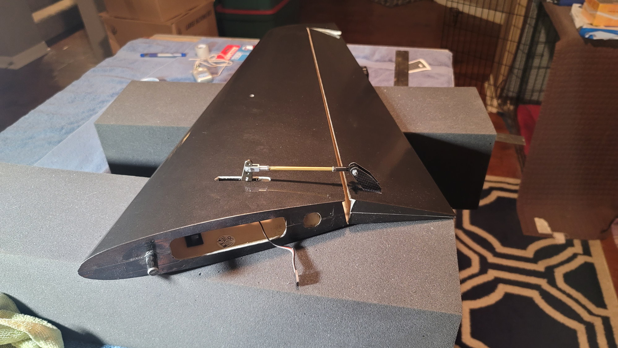
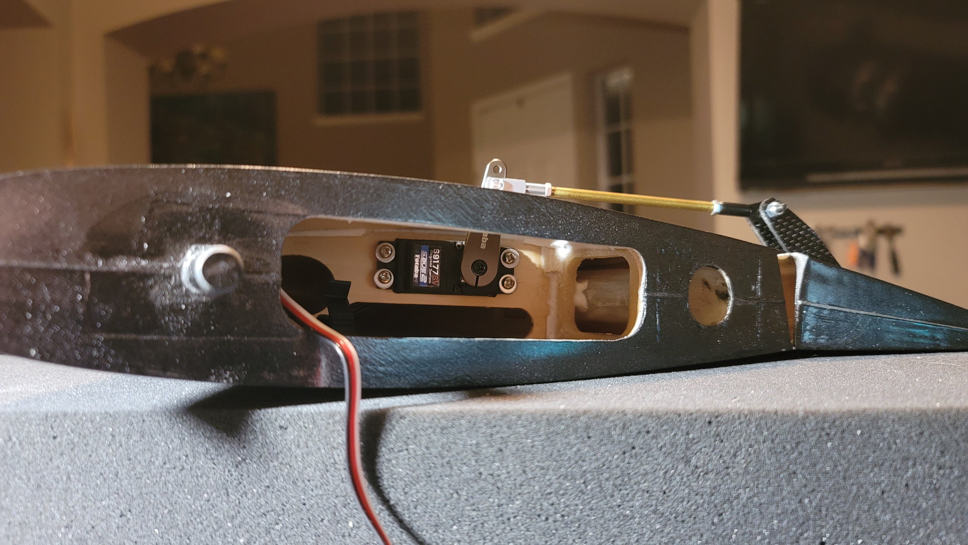
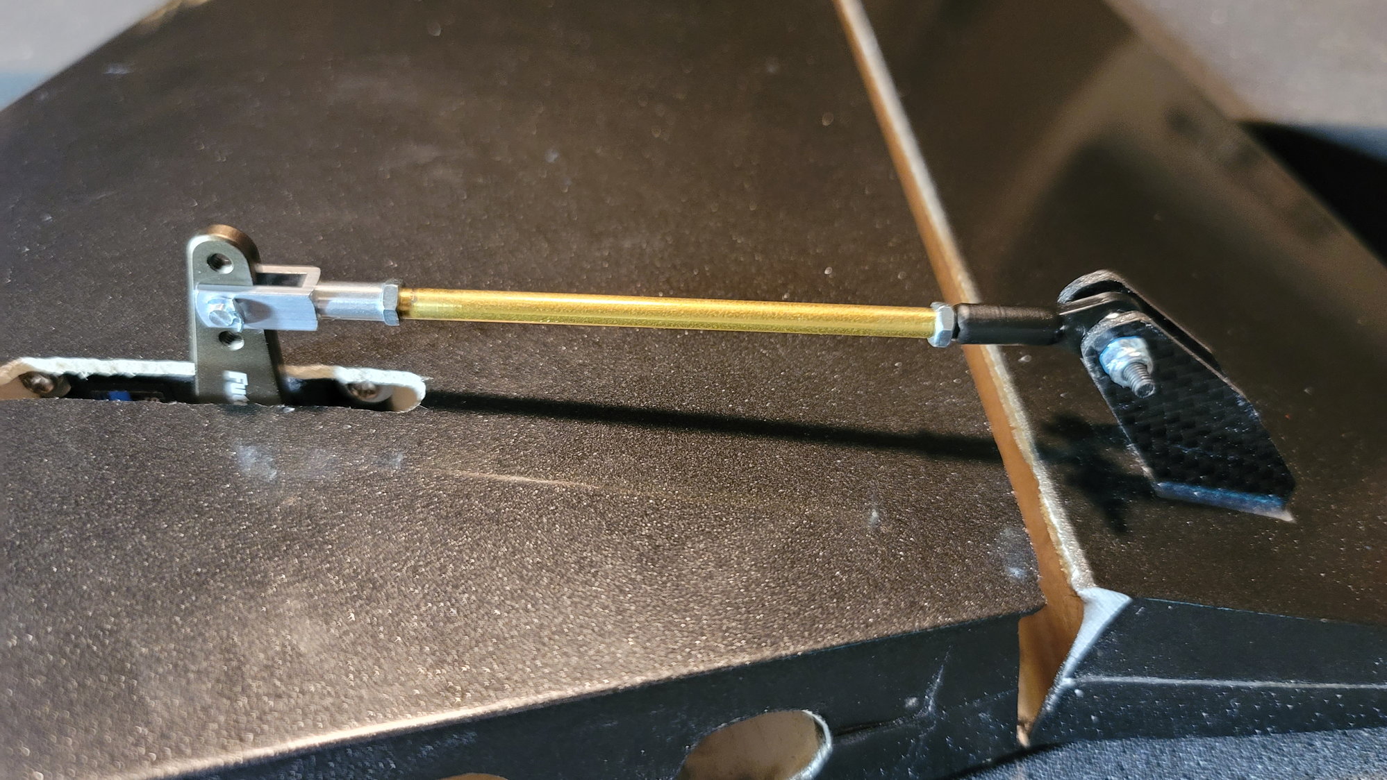
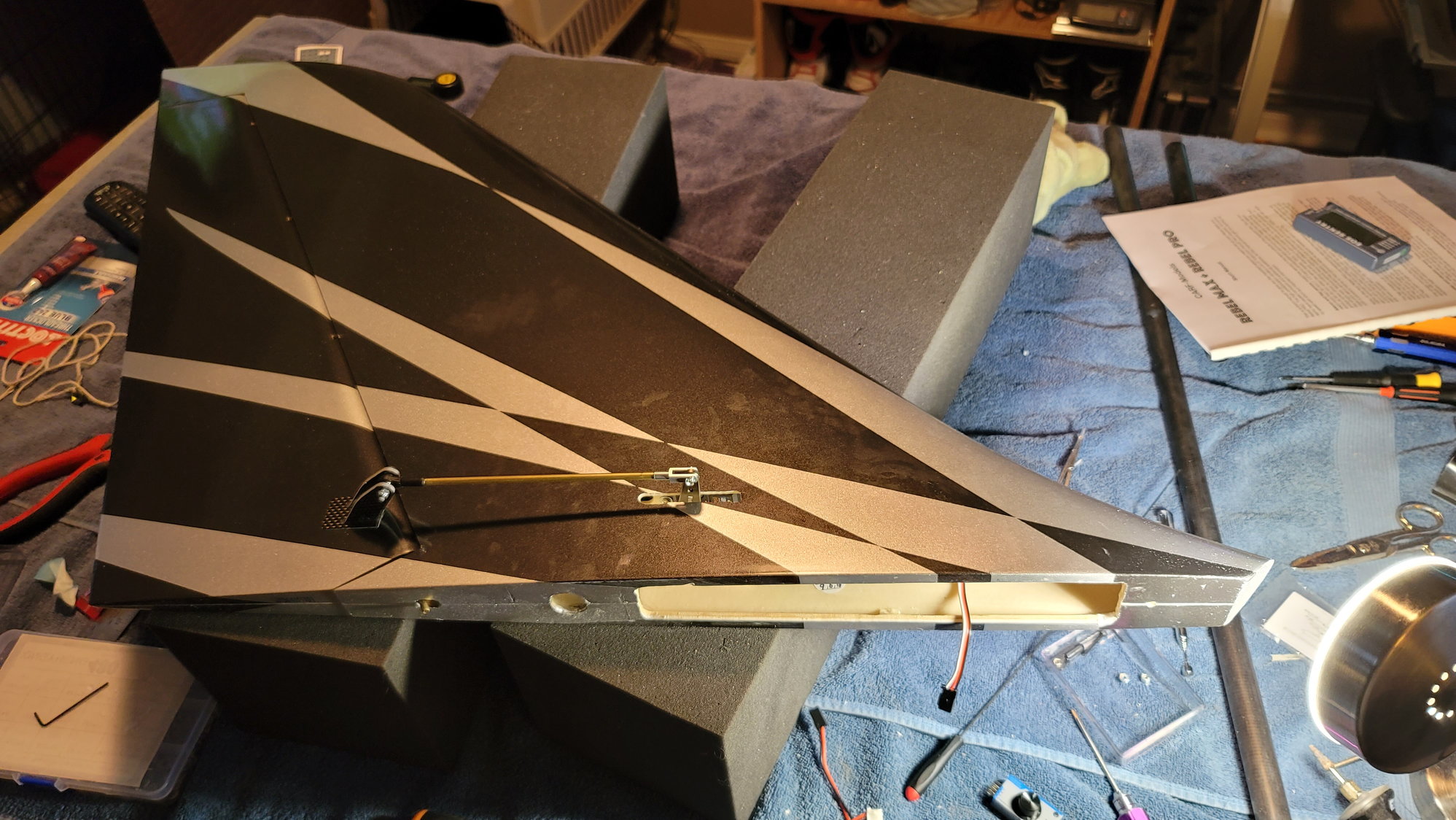
There's very little that's remarkable about installing the servos in the stabs and fin. Very straightforward and the bags that come with the Max are clearly labeled so that there's no confusion on what part goes where. Based on the pictures on the CARF site for the stabs, they mounted their servos to have the shortest amount of pushrod so, mount the servo arm such that it's closest to the trailing edge. This, not ironically, matched up perfectly to the length of the supplied push rods. One small word of caution here. You WILL be cutting out the slit that's provided for the servo arm. It's there but not much fits through it. If you have to lengthen the slit towards the rear, be careful not to cut too far back as you'll cut through some carbon fiber as well as the rear spar. I used 1.25" arms which, arguably, were longer than necessary to achieve the 30-35mm throw they suggest for the elevator but I did this intentionally. I like a lot of elevator and by a lot, I don't mean 3D amounts but even after flying for 30+ years, I can't stand to be on the backside of a loop or on a downline vertical and pull and "feel like" I don't have enough elevator or it takes a lot of the stick to come around. If I want response, I want response right now. So, I have the ability to get more throw if I need it without changing out the arms. Also, be careful that you don't have so much throw that the elevator control horns contact the stabilizer skin at full down elevator.
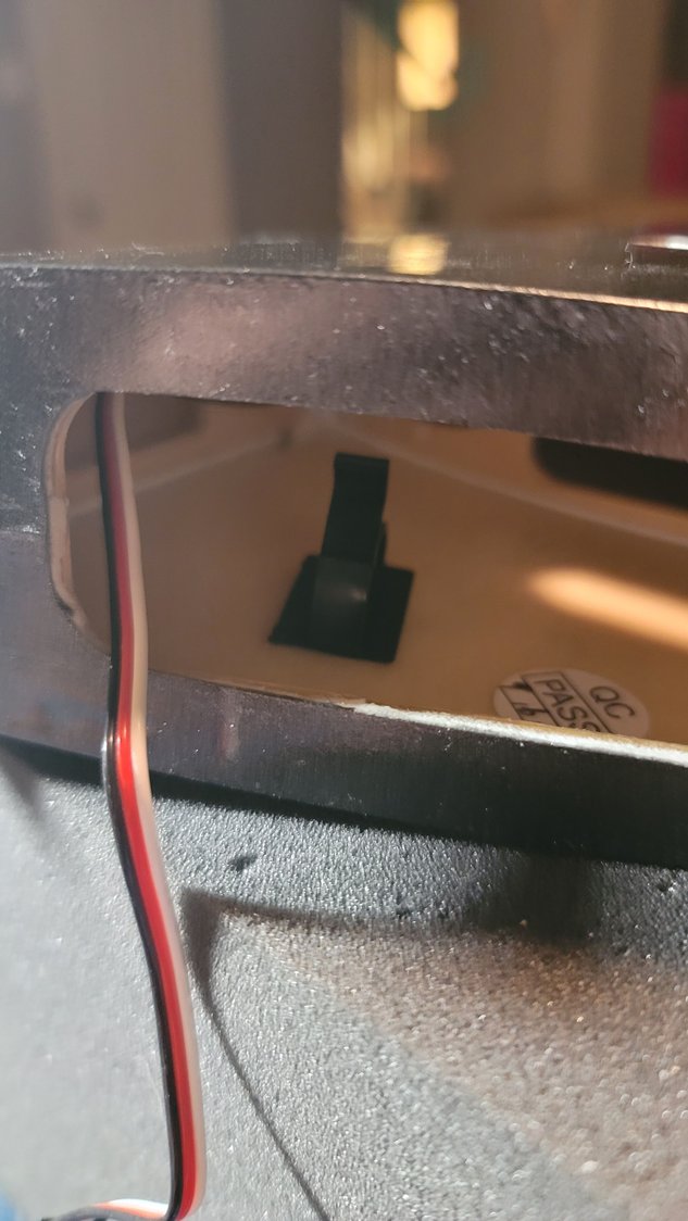
The vertical fin, if it's even possible, was easier than the stabs. Drop the servo in with the servo arm facing the rear of the plane. Here too, I used an 1.25" arm which isn't necessary to get the 60-65mm of travel for the rudder but I'm setting this plane up to fly F3S and, hopefully, the F-Sequence. There's a maneuver in there that will be....interesting to do without thrust vectoring so I wanted the ability to increase it if needed. Again, watch the rudder control horn and make sure it doesn't come in contact with the fin's skin. What I have noticed, however, is by doing this, the cover that comes with the plane will not cover the servo arm and slit that also has to be expanded. It's not awful looking but I think it does look much better with the tiny plastic cover on. What I will do is get enough throw to complete the maneuvers. If I can use a smaller 1" arm, the covering will be perfect for it and that'll take care of that. Time will tell.
As you can see, I'm leaving the male ends of the servos "loose' in the stabs and fin such that I can disconnect them. They will be held in with the little cable hooks. While I'm not a big fan of having to take apart aircraft to transport, even with my 12' V-Nose trailer, this one is just too big not to and I want to be able to unplug the stabs and fin for transport to minimize any hangar rash.
Hopefully before Thanksgiving, I will have the wiring run and tied up through the aft section of the fuselage. This will feed to another AMP connector where the two pieces of the fuselage join. I'm trying to be patient so that I can better learn to make connectors from the PowerBox wiring to the male leads that will plug into the Mercury power distribution board and gyro. Canadian Man promises there's a video coming for this. No pressure Jonathan!
There's very little that's remarkable about installing the servos in the stabs and fin. Very straightforward and the bags that come with the Max are clearly labeled so that there's no confusion on what part goes where. Based on the pictures on the CARF site for the stabs, they mounted their servos to have the shortest amount of pushrod so, mount the servo arm such that it's closest to the trailing edge. This, not ironically, matched up perfectly to the length of the supplied push rods. One small word of caution here. You WILL be cutting out the slit that's provided for the servo arm. It's there but not much fits through it. If you have to lengthen the slit towards the rear, be careful not to cut too far back as you'll cut through some carbon fiber as well as the rear spar. I used 1.25" arms which, arguably, were longer than necessary to achieve the 30-35mm throw they suggest for the elevator but I did this intentionally. I like a lot of elevator and by a lot, I don't mean 3D amounts but even after flying for 30+ years, I can't stand to be on the backside of a loop or on a downline vertical and pull and "feel like" I don't have enough elevator or it takes a lot of the stick to come around. If I want response, I want response right now. So, I have the ability to get more throw if I need it without changing out the arms. Also, be careful that you don't have so much throw that the elevator control horns contact the stabilizer skin at full down elevator.
The vertical fin, if it's even possible, was easier than the stabs. Drop the servo in with the servo arm facing the rear of the plane. Here too, I used an 1.25" arm which isn't necessary to get the 60-65mm of travel for the rudder but I'm setting this plane up to fly F3S and, hopefully, the F-Sequence. There's a maneuver in there that will be....interesting to do without thrust vectoring so I wanted the ability to increase it if needed. Again, watch the rudder control horn and make sure it doesn't come in contact with the fin's skin. What I have noticed, however, is by doing this, the cover that comes with the plane will not cover the servo arm and slit that also has to be expanded. It's not awful looking but I think it does look much better with the tiny plastic cover on. What I will do is get enough throw to complete the maneuvers. If I can use a smaller 1" arm, the covering will be perfect for it and that'll take care of that. Time will tell.
As you can see, I'm leaving the male ends of the servos "loose' in the stabs and fin such that I can disconnect them. They will be held in with the little cable hooks. While I'm not a big fan of having to take apart aircraft to transport, even with my 12' V-Nose trailer, this one is just too big not to and I want to be able to unplug the stabs and fin for transport to minimize any hangar rash.
Hopefully before Thanksgiving, I will have the wiring run and tied up through the aft section of the fuselage. This will feed to another AMP connector where the two pieces of the fuselage join. I'm trying to be patient so that I can better learn to make connectors from the PowerBox wiring to the male leads that will plug into the Mercury power distribution board and gyro. Canadian Man promises there's a video coming for this. No pressure Jonathan!
The following 2 users liked this post by smcharg:
AEROSHELDON (11-22-2021),
Canadian Man (12-15-2021)
11-23-2021, 12:30 PM
#48
Senior Member
Hello Scott, Thanks for posting photos of your Max plane .
Just curious as to the stab and horizontal servo, why you didn't centre the arm square to the servo.
I realize that you probably have to carve some foam skin away to get the max deflection, those 177 can be centred with your transmitter as a good friend show me how he does his with a Futaba 32.
Canada Man who I fly, does make it easy attaching servo pins, one of the key tools is the Powerbox wire crimper which makes quick work fastening the pins in one go.
I think after the Huracan build, wish should be done soon, he might be doing some of these small videos, I should ask as he's finishing the inside of his new home off.
Rusty
Last edited by Skunkwrks; 11-23-2021 at 12:35 PM.
11-23-2021, 12:37 PM
#49
Thread Starter
My Feedback: (1)
Hello Scott, Thanks for posting photos of your Max plane .
Just curious as to the stab servo, why you didn't centre the arm square to the servo.
I realize that you probably have to carve some foam skin away to get the max deflection, those 177 can be centred with your transmitter as a good friend show me how he does his with a Futaba 32.
Rusty
Just curious as to the stab servo, why you didn't centre the arm square to the servo.
I realize that you probably have to carve some foam skin away to get the max deflection, those 177 can be centred with your transmitter as a good friend show me how he does his with a Futaba 32.
Rusty
Maybe I'm confused by your question but, the servo arms are centered 90 degrees perpendicular to the control surface. It may not look that way in the pictures because the servos are unpowered and the control surfaces are laying down on the table (gravity). If they are off at all, I'll use the Futaba 32MZ to fix it. At least, they are as centered as I can mechanically make them. On Futaba's, there are only 25 teeth so getting 100% perfect without the use of sub-trim is difficult but, they should be in good shape.
I wish I could have come up with something good like, I was building in aileron differential but would have been called out very quickly around here!
Best,
Scott
Last edited by smcharg; 11-23-2021 at 05:15 PM.
11-23-2021, 12:50 PM
#50
Thread Starter
My Feedback: (1)
When I got home last night, I did go ahead and pull the wires through for the horizontal stabs. I bought the high temp sleeve from BVM and ran the PowerBox wire through it. It's cut to length so that it is enough to put the female end of a servo connector on the stab's root rib on the fuse and simply plug it into the male end of the servo. This will make it simple to take apart and put together. I'll probably put a small zip-tie on the end so that it can't slip back into the fuse where it'd get pretty hot and be a bit of a pain to feed back through. The other end is held in with the typical cable tie you've seen me use before and away from where the pipe is. It will be connected to a 10-pin AMP connector which will connect the tail servos to the rest of the wire in the front half of the fuse.
I'm waiting on some more grommets from Amazon, supposedly arriving today and I'll do the vertical fin tonight. It'll be done exactly the same way. We'll be traveling for Thanksgiving so I'll update the thread upon my return.
Have a Happy Thanksgiving all!
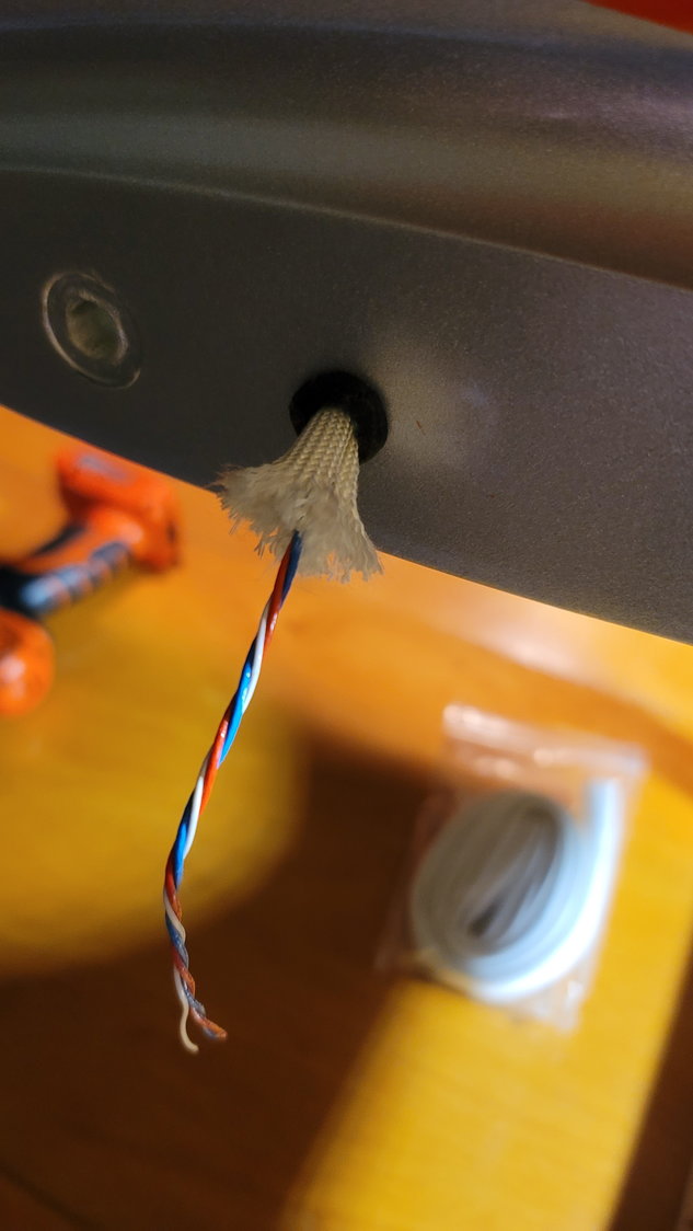
High temp sheath for PowerBox wire from BVM. This end will get the female servo connector to plug into the stabs. A small grommet is used for the finishing touch. No glue, just very careful drilling and a snug fit.
This is the rear of the fuse inverted to show where the wires penetrate the stab's fuse root through the grommet.
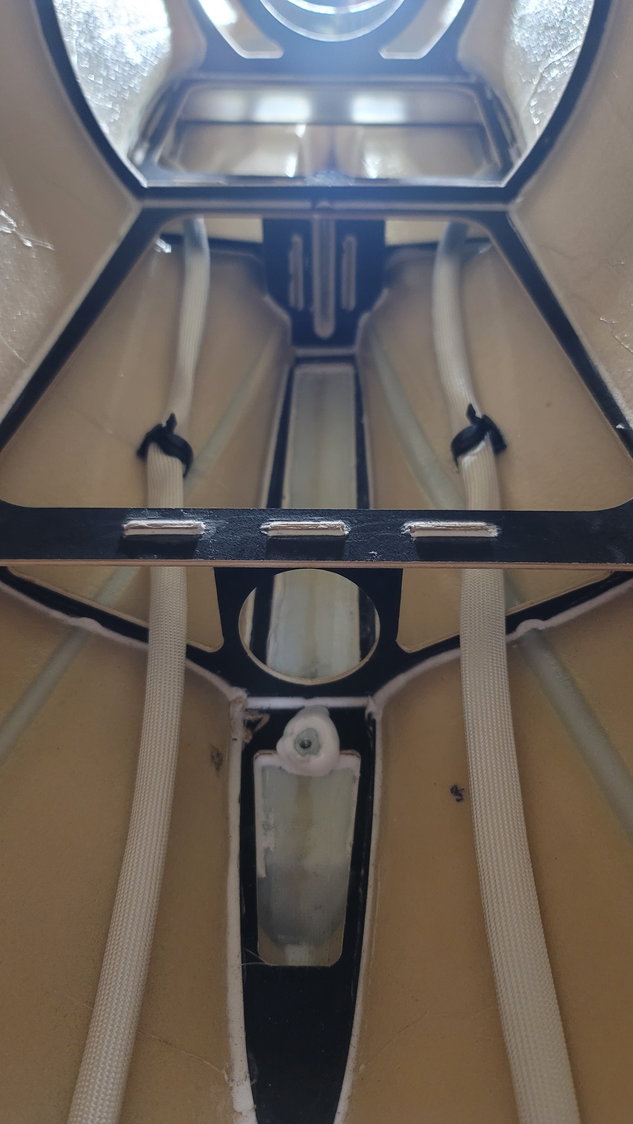
Front of the rear fuse looking back and fuse is inverted. High temp sleeves and wires run and away from the pipe. The vertical fin wire hole will be drilled behind the first bulkhead you see in the picture using the same technique
I'm waiting on some more grommets from Amazon, supposedly arriving today and I'll do the vertical fin tonight. It'll be done exactly the same way. We'll be traveling for Thanksgiving so I'll update the thread upon my return.
Have a Happy Thanksgiving all!
High temp sheath for PowerBox wire from BVM. This end will get the female servo connector to plug into the stabs. A small grommet is used for the finishing touch. No glue, just very careful drilling and a snug fit.
This is the rear of the fuse inverted to show where the wires penetrate the stab's fuse root through the grommet.
Front of the rear fuse looking back and fuse is inverted. High temp sleeves and wires run and away from the pipe. The vertical fin wire hole will be drilled behind the first bulkhead you see in the picture using the same technique