


CARF Rebel MAX - Build Thread
 11-23-2021, 01:10 PM
#51
Senior Member
Howdy Rusty,
Maybe I'm confused by your question but, the servo arms are centered 90 degrees perpendicular to the servo. It may not look that way in the pictures because the servos are unpowered and the control surfaces are laying down on the table (gravity). If they are off at all, I'll use the Futaba 32MZ to fix it. On Futaba's, there are only 25 teeth so getting 100% perfect without the use of sub-trim is difficult. Again, these are as perfectly centered as I can get them until I use the radio but they should be in good shape.
I wish I could have come up with something good like, I was building in aileron differential but would have been called out very quickly around here!
Best,
Scott
I've experienced centring a 25 tooth arm on my MKS 599 that isn't programmable in my Imac planes,and with every spline moved it's 14.4 degrees of movement so you have go through a few arms to get it close to center and the sub trim the rest . I've used a quad current meter from Fromeco to balance multiple servos through my servo balance program in the Jeti so each servo is drawing nearly the same current through the full travel range. Time-consuming but worth it.
With the new Transmitters or even JR servo programmer, this has become an obsolete tool for the new stuff of equipment.
That Fut 32 should have all that programing for crow, differential and such, I know my Jeti does this but lacks true servo programming capabilities, it's amazing how you can fine-tune every aspect through that computer adding in aileron deflection to slow down the plane.
Rusty

The following users liked this post:
smcharg (11-23-2021)
11-23-2021, 01:54 PM
#52

Forget centring the arm to the case, it should be done to be 90 degrees the pushrod at surface neutral, we are taking a rotary movement into linear.
I buy double sided arms where possible, try both sides to get near zero subtrim and cut off the unused side.
Back in the early days of CCPM helicopters I would take the servo apart and move gears a tooth or two to match all servos. JR were again king with the Super servo arm set which had 5 numbers with staggered splines to allow near perfect centring from trying a different arm number.
11-23-2021, 05:11 PM
#53
12-07-2021, 09:15 AM
#54
Thread Starter
My Feedback: (1)

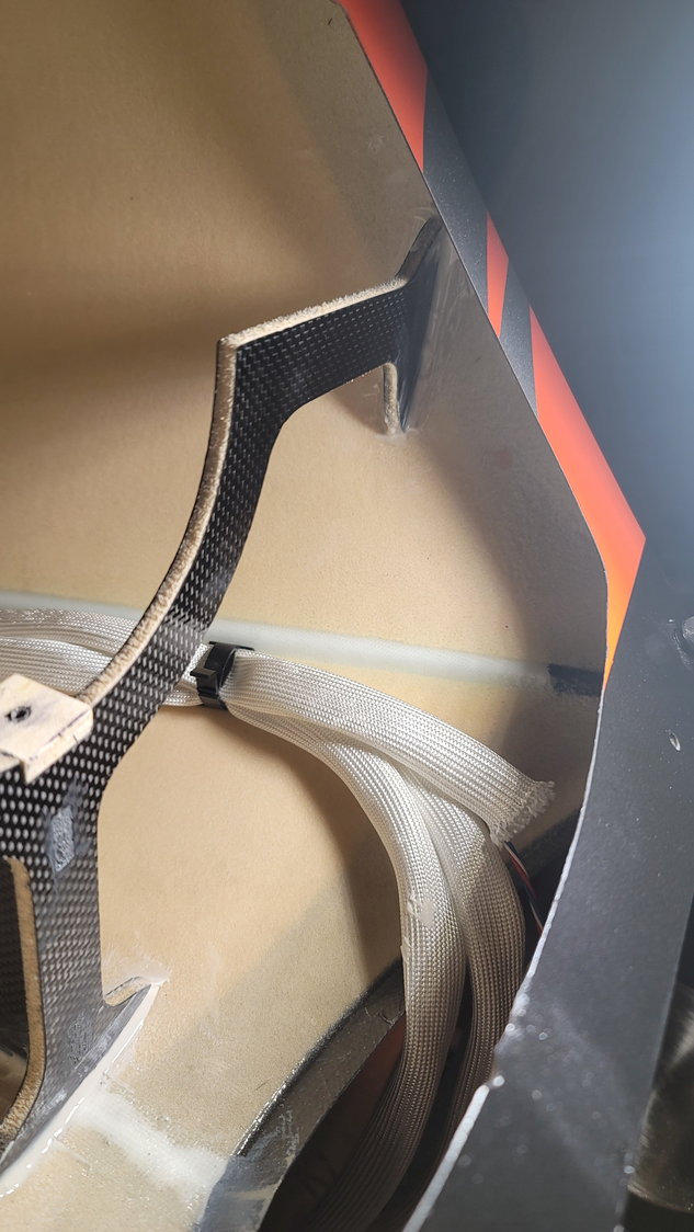
Over the past week or so, I've got some stuff done on this massive jet. I left off with running the servo wires through the aft section of the fuselage and encasing them in the BVM high-temp sleeves. I drilled holes into the fuselage where the stabs and vertical fin connect and inserted rubber grommets in which to pass through the servo wires. The wires, when flying, will reside in the cavernous stabs and vertical fin so that they do not slip back into the fuselage and next to the hot thrust tube. To secure these in hopes of preventing this, I've taken some small zip ties and put them on the connections so that it cannot slip. Lastly, I placed some cable holders on the top of the fuselage inside to hold each of the three servo wire bundles to run to the front of the rear fuse where they will be connected to the AMP 10-pin connector so that the aft fuse is easily removed for transportation.
The next step that is now in-process is to actually mount the thrust tube and former next to the bell mouth. The rear former is already set by CARF and, assuming you use the Rebel MAX thrust tube, fits snug and precisely in that rear former. I had to sand just slightly the bottom portion of that former but only to allow the "rivet" to pass through on the bottom of the tube (this shows you the precise fit for this thrust tube). This should make it very easy to align as we only have to worry about the front former.
This part is a little scary for me to be honest. I spent a lot of time on the phone with my buddy Jack who is a few steps ahead of me to understand and mentally visualize the process. As I'm progressing, it's not nearly as bad as I had envisioned but is a little tedious. First, you need to assemble the former, itself. It's in its own bag clearly marked from CARF and consists of 3 pieces; the former itself which will attach to the sides and top of the fuselage, a triangular support the fits into the former and goes from the former towards the rear of the fuse and also gets glued to the top of the fuse internally, and a small plywood block which has its spot already set for you between the former and brace. This is used to screw the thrust tube into and how CARF wants you to secure the thrust tube. It is a single screw, which is interesting, but seems to work well. Again, assuming you are using the CARF thrust tube, you will have to drill a hole for the screw into the tube, itself. We'll get to the importance of that shortly. So, I've assembled these three pieces and glued them together with Hysol 9460 and allowed to cure overnight. (I forgot to take pictures of this glued together but will show it in the next post)
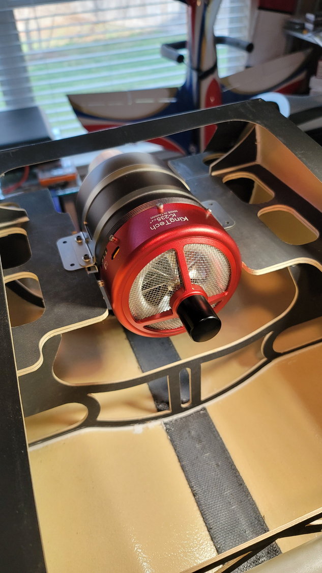
Next, we need to temporarily mount the turbine in the front half of the fuse. I'm using the KingTech K235G4+. I had to trim 6mm on each engine rail in order for the engine to mount flush to the rails. I trimmed this with a Dremel cutoff wheel and cleaned it up with the sanding bit. This was for clearance of the nuts and washers that hold the clamp of the engine. There is still plenty of material on the rails to then permanently mount the engine. Remember, this step is only for temporarily mounting the engine to align the thrust tube and is not to set the distance of the exhaust port of the turbine to the thrust tube so distance is not important here. What is absolutely important is the side to side alignment of the engine to the fuselage so that we can set the thrust tube properly. Keep in mind that each turbine is going to be a little different and this is only how I did the KT235. I placed the engine on the engine rails and used a laser alignment tool I bought on Amazon for tens of dollars and have used it for everything from firewall alignment to picture hanging. It is a great little tool!
6mm cut out on each rail to allow the KingTech K235G4+ to mount flush to the rails
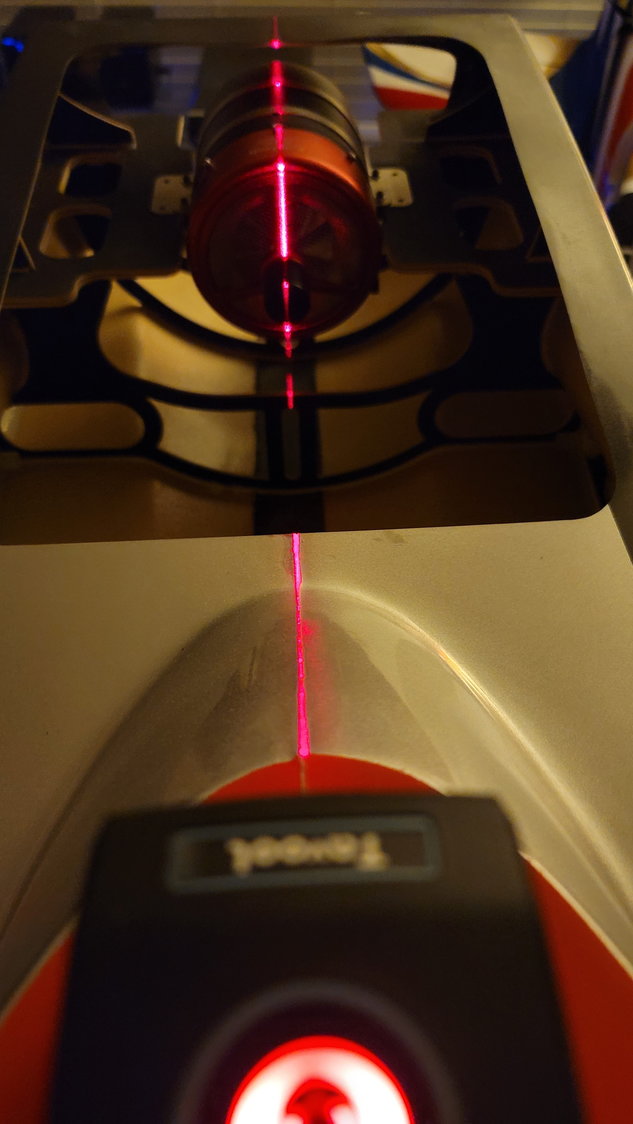
My little laser tool for alignment. The joint of the two halves of the fuse is perfectly centered and what I used as the alignment.
Next, I took some 3" clamps to secure the engine to the rails so that it did not move for the next part. The funny thing about clamps...the smaller you use, the shorter the throat is. I could not make 2" clamps work well because of this. Caution when using larger clamps - be careful not to tear up the sides of the fuse flange where the canopy sits. Luckily, I saw this before there was damage and all is well. Now that the turbine is aligned and centered in the fuse we can move on.
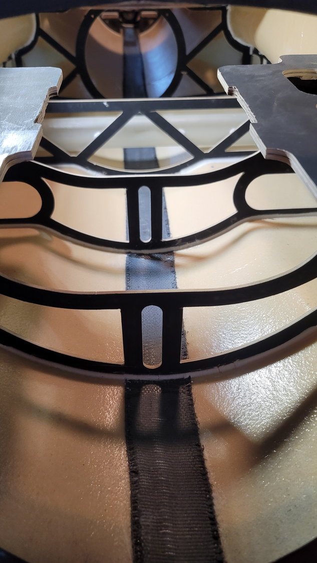
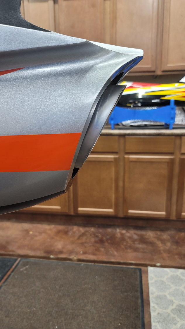
The next step is to insert the former into the rear fuse with the thrust tube. I found it easy to install the tube and then just slide the former in from the front horizontally and then stand up the former. The fit will be tight and the mounting point will not be far behind the opening of the front of the rear fuse. Without any sanding so far, I am able to fit the former such that I am ready for trial fitting. Our manual tells us that we want 10-15mm of the thrust tube sticking out of the back of the aircraft. I've elected to measure at the bottom of the fuse to get that distance as this tube is angled. This distance will also help you to understand where the front of the pipe will be and help you set the position of the former fairly easily.
Now, we must mount the rear fuselage to the front fuselage. This is easily done as there are 4 socket head screws that are already installed in the aft fuse and slide down into the slots in the front portion of the fuse. They should already be set and you shouldn't have to tighten or loosen these. If you do, make sure to put Locktite back on them. I didn't have to touch them and they were perfectly set. The aft fuse is held onto the front fuse by these four bolts as well as 3 smaller bolts, two in the top and one in the bottom. These 3 bolts are removable and what you would take out in order to separate the fuselage into its two pieces for transportation. For this part, I am not installing them as the 4 semi-permanent bolts will suffice. Note that you will, most likely, have to take the fuse apart a few times to get everything set.
I have found that I will probably have to grind a little of the rear portion of the engine rails out so that the bellmouth does not contact the rails when the position is set, again, to obtain the 10-15mm of pipe sticking out the back of the plane. Once assembled, I was able to get my first look at where the former must be positioned. Again, without any sanding, I'm pretty close to well-centered but I do feel the front of the pipe will need to be raised slightly. To do this, I will sand down the top of the former and support where it contacts the top of the fuse. Once that's finalized, I will make sure that I'm good side-to-side as well. The former will be easy to sand as it's a type of carbon laminated foam. This is the next step that I will do this week. When I get close to what I want to make sure the turbine and the tube are perfectly aligned, I will drill the hole into the top of the tube where it will connect to the former using the previously discussed screw and hardwood block in the former. This is going to be important as, again, this tube is angled at the exhaust. If you don't get it in the correct place, when you mount the tube to the former, it is possible that the angled portion....the "longest" part, if you will, will not be at the top so measure 50 times and drill once. That step will come in the next post. The plan is to do that, get it perfectly aligned, tack glue it in place with CA and then remove the aft fuse, pull the thrust tube out and glue in the former permanently with Hysol 9462. Why the two glues you may ask? 9460 is grey/black and 9462 is white. That is the difference. I'll use 9462 to glue in the former to the fuse so that it matches all the other formers from CARF. That episode is coming soon!
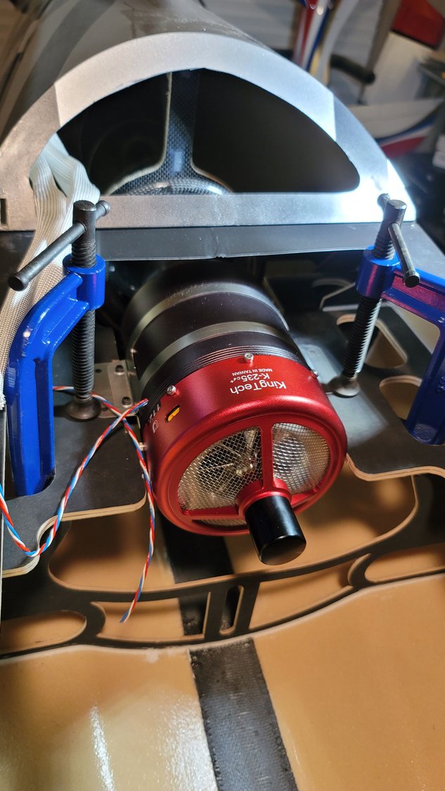
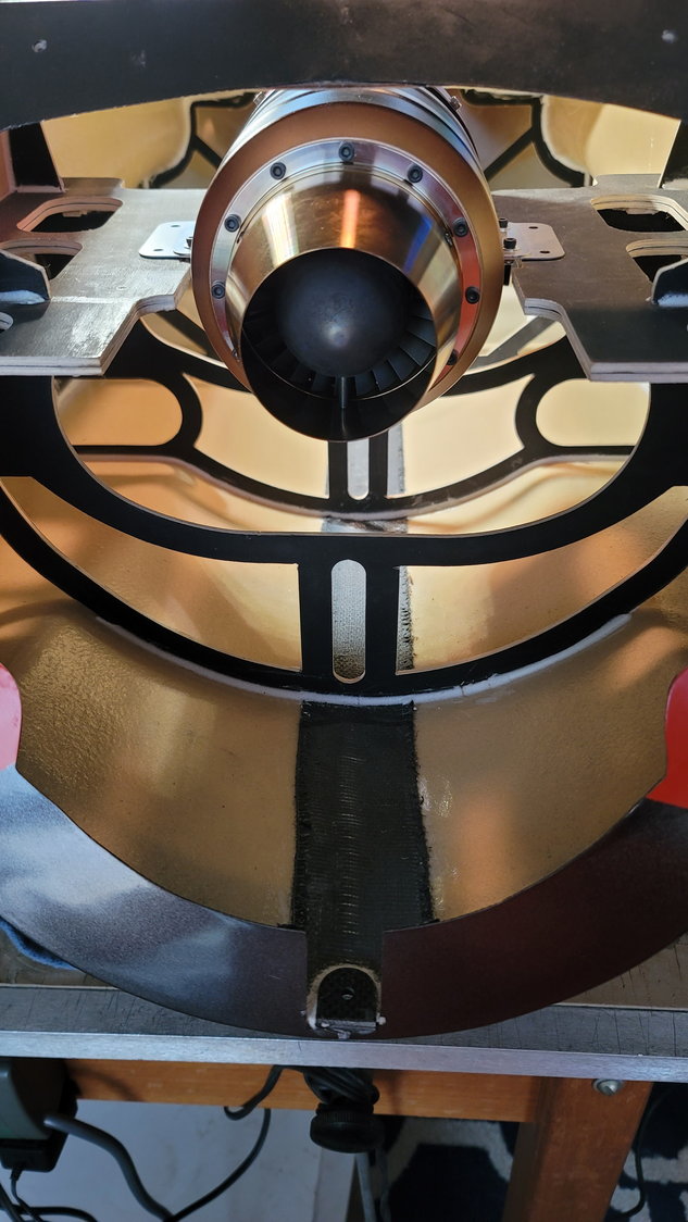
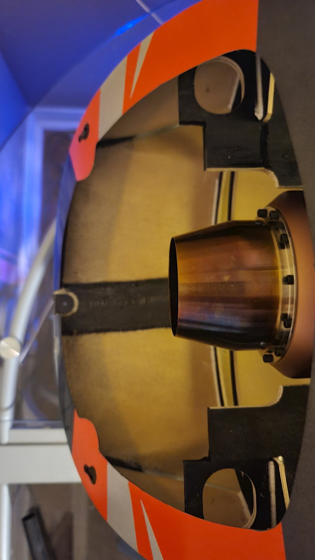
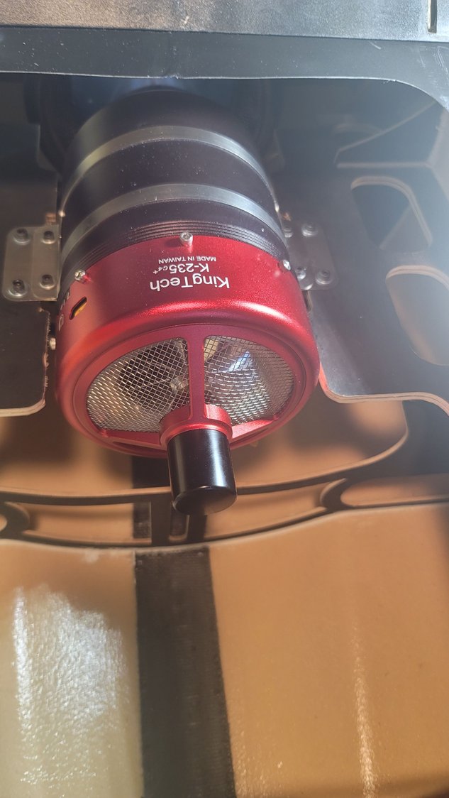
Turbine temporarily mounted for thrust tube alignment.
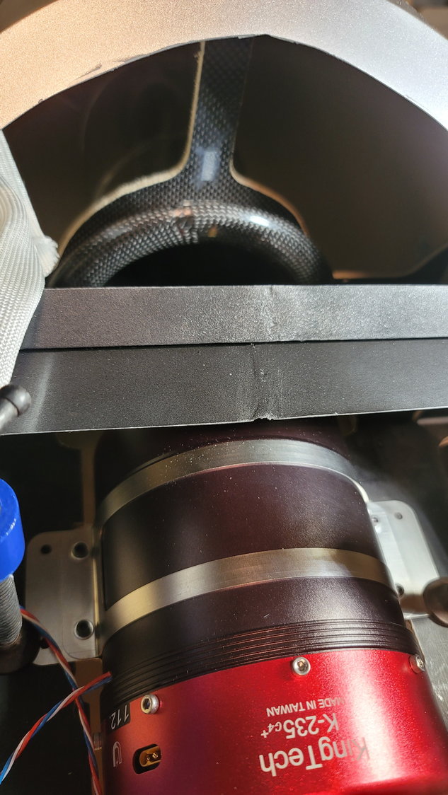
This is the first fit of the former. It is just wedged in and is pretty darn close to being right
It's hard to tell in the picture unless you zoom in but I want to raise the front of the pipe slightly so that the alignment is 100% as close to perfect as I can get it.
One thing I forgot to point out. On my Max, the rudder hinge is a brass tube and already installed. It is very nice and would make for rudder removal quick and easy. What I found is that the tube is a little long and sticks out the bottom or you have a ton sticking out on top. I briefly considered drilling a hole into the fuse where the vertical fin sits to make clearance for the hinge to sit in. After some consideration, I changed my mind as, if I did this, the hinge could potentially slip down into the fuse near the pipe. While the hinge is tight, it's not "held in" in any other way. Because of this, I pushed the hinge in at the bottom where there is a considerable amount sticking out of the top. I'll either cut this at the top so that there isn't much sticking out OR, I'll paint the tube red and make it a little beacon light! Just kidding....or not. Maybe y'all have some ideas on how to deal with this that I could incorporate.
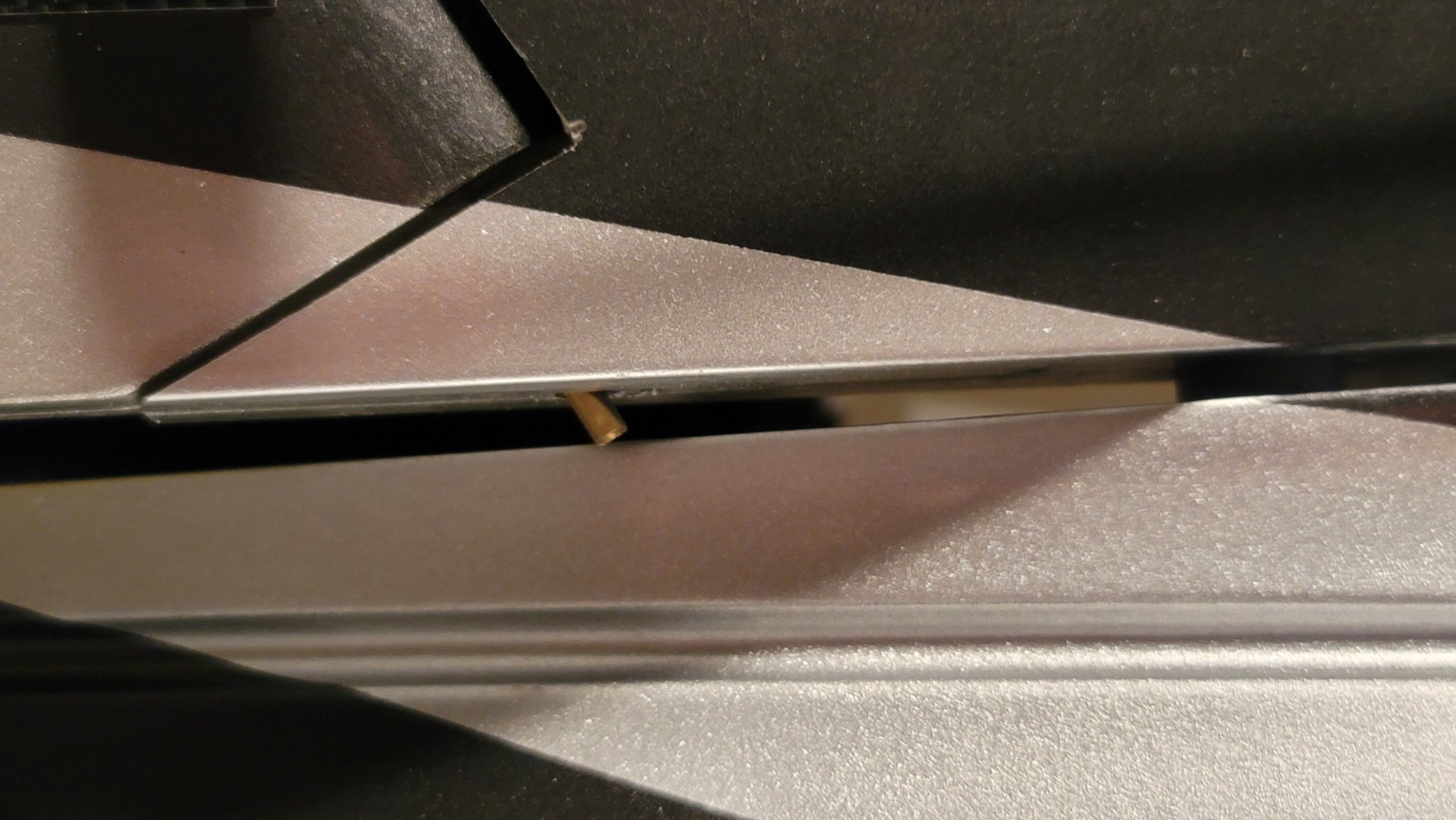
If the top is fairly flush, this is what sticks out the bottom and must be dealt with in some way. I elected to push it in from the bottom and allow the excess to stick out the top...for now.
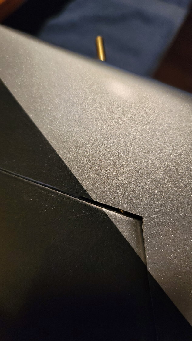
When pushed up from the bottom, this is how much is sticking out of the top. Thoughts and ideas?
The next step that is now in-process is to actually mount the thrust tube and former next to the bell mouth. The rear former is already set by CARF and, assuming you use the Rebel MAX thrust tube, fits snug and precisely in that rear former. I had to sand just slightly the bottom portion of that former but only to allow the "rivet" to pass through on the bottom of the tube (this shows you the precise fit for this thrust tube). This should make it very easy to align as we only have to worry about the front former.
This part is a little scary for me to be honest. I spent a lot of time on the phone with my buddy Jack who is a few steps ahead of me to understand and mentally visualize the process. As I'm progressing, it's not nearly as bad as I had envisioned but is a little tedious. First, you need to assemble the former, itself. It's in its own bag clearly marked from CARF and consists of 3 pieces; the former itself which will attach to the sides and top of the fuselage, a triangular support the fits into the former and goes from the former towards the rear of the fuse and also gets glued to the top of the fuse internally, and a small plywood block which has its spot already set for you between the former and brace. This is used to screw the thrust tube into and how CARF wants you to secure the thrust tube. It is a single screw, which is interesting, but seems to work well. Again, assuming you are using the CARF thrust tube, you will have to drill a hole for the screw into the tube, itself. We'll get to the importance of that shortly. So, I've assembled these three pieces and glued them together with Hysol 9460 and allowed to cure overnight. (I forgot to take pictures of this glued together but will show it in the next post)
Next, we need to temporarily mount the turbine in the front half of the fuse. I'm using the KingTech K235G4+. I had to trim 6mm on each engine rail in order for the engine to mount flush to the rails. I trimmed this with a Dremel cutoff wheel and cleaned it up with the sanding bit. This was for clearance of the nuts and washers that hold the clamp of the engine. There is still plenty of material on the rails to then permanently mount the engine. Remember, this step is only for temporarily mounting the engine to align the thrust tube and is not to set the distance of the exhaust port of the turbine to the thrust tube so distance is not important here. What is absolutely important is the side to side alignment of the engine to the fuselage so that we can set the thrust tube properly. Keep in mind that each turbine is going to be a little different and this is only how I did the KT235. I placed the engine on the engine rails and used a laser alignment tool I bought on Amazon for tens of dollars and have used it for everything from firewall alignment to picture hanging. It is a great little tool!
6mm cut out on each rail to allow the KingTech K235G4+ to mount flush to the rails
My little laser tool for alignment. The joint of the two halves of the fuse is perfectly centered and what I used as the alignment.
Next, I took some 3" clamps to secure the engine to the rails so that it did not move for the next part. The funny thing about clamps...the smaller you use, the shorter the throat is. I could not make 2" clamps work well because of this. Caution when using larger clamps - be careful not to tear up the sides of the fuse flange where the canopy sits. Luckily, I saw this before there was damage and all is well. Now that the turbine is aligned and centered in the fuse we can move on.
The next step is to insert the former into the rear fuse with the thrust tube. I found it easy to install the tube and then just slide the former in from the front horizontally and then stand up the former. The fit will be tight and the mounting point will not be far behind the opening of the front of the rear fuse. Without any sanding so far, I am able to fit the former such that I am ready for trial fitting. Our manual tells us that we want 10-15mm of the thrust tube sticking out of the back of the aircraft. I've elected to measure at the bottom of the fuse to get that distance as this tube is angled. This distance will also help you to understand where the front of the pipe will be and help you set the position of the former fairly easily.
Now, we must mount the rear fuselage to the front fuselage. This is easily done as there are 4 socket head screws that are already installed in the aft fuse and slide down into the slots in the front portion of the fuse. They should already be set and you shouldn't have to tighten or loosen these. If you do, make sure to put Locktite back on them. I didn't have to touch them and they were perfectly set. The aft fuse is held onto the front fuse by these four bolts as well as 3 smaller bolts, two in the top and one in the bottom. These 3 bolts are removable and what you would take out in order to separate the fuselage into its two pieces for transportation. For this part, I am not installing them as the 4 semi-permanent bolts will suffice. Note that you will, most likely, have to take the fuse apart a few times to get everything set.
I have found that I will probably have to grind a little of the rear portion of the engine rails out so that the bellmouth does not contact the rails when the position is set, again, to obtain the 10-15mm of pipe sticking out the back of the plane. Once assembled, I was able to get my first look at where the former must be positioned. Again, without any sanding, I'm pretty close to well-centered but I do feel the front of the pipe will need to be raised slightly. To do this, I will sand down the top of the former and support where it contacts the top of the fuse. Once that's finalized, I will make sure that I'm good side-to-side as well. The former will be easy to sand as it's a type of carbon laminated foam. This is the next step that I will do this week. When I get close to what I want to make sure the turbine and the tube are perfectly aligned, I will drill the hole into the top of the tube where it will connect to the former using the previously discussed screw and hardwood block in the former. This is going to be important as, again, this tube is angled at the exhaust. If you don't get it in the correct place, when you mount the tube to the former, it is possible that the angled portion....the "longest" part, if you will, will not be at the top so measure 50 times and drill once. That step will come in the next post. The plan is to do that, get it perfectly aligned, tack glue it in place with CA and then remove the aft fuse, pull the thrust tube out and glue in the former permanently with Hysol 9462. Why the two glues you may ask? 9460 is grey/black and 9462 is white. That is the difference. I'll use 9462 to glue in the former to the fuse so that it matches all the other formers from CARF. That episode is coming soon!
Turbine temporarily mounted for thrust tube alignment.
This is the first fit of the former. It is just wedged in and is pretty darn close to being right
It's hard to tell in the picture unless you zoom in but I want to raise the front of the pipe slightly so that the alignment is 100% as close to perfect as I can get it.
One thing I forgot to point out. On my Max, the rudder hinge is a brass tube and already installed. It is very nice and would make for rudder removal quick and easy. What I found is that the tube is a little long and sticks out the bottom or you have a ton sticking out on top. I briefly considered drilling a hole into the fuse where the vertical fin sits to make clearance for the hinge to sit in. After some consideration, I changed my mind as, if I did this, the hinge could potentially slip down into the fuse near the pipe. While the hinge is tight, it's not "held in" in any other way. Because of this, I pushed the hinge in at the bottom where there is a considerable amount sticking out of the top. I'll either cut this at the top so that there isn't much sticking out OR, I'll paint the tube red and make it a little beacon light!
Just kidding....or not. Maybe y'all have some ideas on how to deal with this that I could incorporate.If the top is fairly flush, this is what sticks out the bottom and must be dealt with in some way. I elected to push it in from the bottom and allow the excess to stick out the top...for now.
When pushed up from the bottom, this is how much is sticking out of the top. Thoughts and ideas?
Last edited by smcharg; 12-07-2021 at 09:39 AM.
The following users liked this post:
Canadian Man (12-15-2021)
12-07-2021, 10:02 PM
#55
Because of the angled hinge I would cut it so the tube is just below the top of the fin. At the bottom where you won’t see Hysol a M3 screw and washer into the tube and recess the fin to allow that to be flush. The fuse will stop the pin dropping down and the washer stop it riding up, the washer and bolt head gives you something to grab if you need to pull the hinge tube out for maintenance
D
D
12-08-2021, 05:08 AM
#56
Thread Starter
My Feedback: (1)
Because of the angled hinge I would cut it so the tube is just below the top of the fin. At the bottom where you won�t see Hysol a M3 screw and washer into the tube and recess the fin to allow that to be flush. The fuse will stop the pin dropping down and the washer stop it riding up, the washer and bolt head gives you something to grab if you need to pull the hinge tube out for maintenance
D
D
12-09-2021, 08:35 AM
#57
Thread Starter
My Feedback: (1)
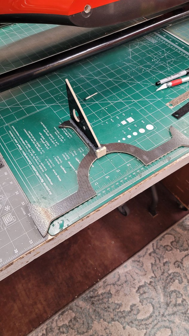
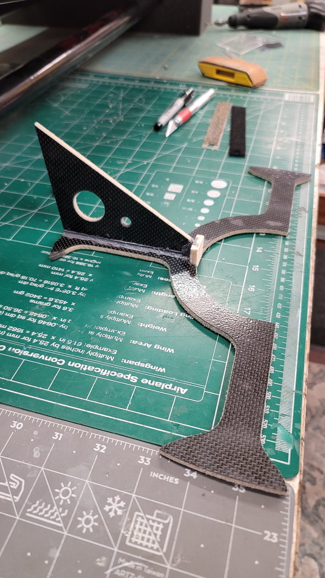
Here are the pictures of the thrust tube former glued together and ready for install
So, last night, I enlisted the help of my buddy Pattratt1 who is a perfectionist when it comes to jets and ways to accomplish things to get them as close to perfect as possible. We live in a fairly small town where Texas A&M is and we are the only two that fly jets in this area. We both usually wind up traveling down to Houston and fly at Bomber Field because our local field isn't really suited for jets. We have no hobby shop and while we have a few very good modelers, no one does jets here. He's become a very good friend to me and we've known each other over a decade. He has my trust.
I told him that I'd like his guidance on permanently mounting and gluing the former in place because it is absolutely necessary to get it set perfectly to align the pipe and the turbine. I've already gone through the steps in my previous post and will just add the nuances here:
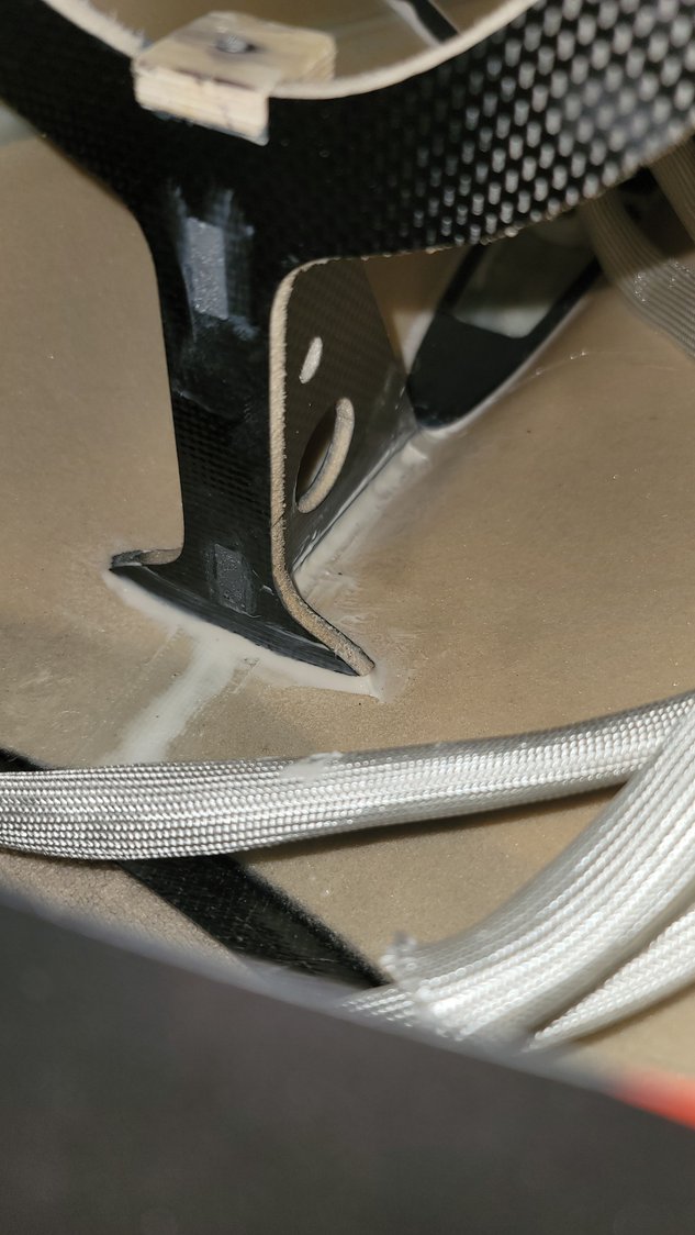
First, to explain again how the two fuse halves assemble. There are 4 bolts that are mounted into the aft section. Then there are 4 "keyhole" slits in the front half of the fuse where the heads of the bolts in the rear section slide into and down. On the inside of these keyhole slits, there is a wood back plate to help hold the aft section. I bring this up because, as I said previously, you do have to take the two halves apart a few times to finish the job and you must be somewhat careful when aligning the two halves. What we found during the initial fitting is that one of the wood pieces had come off of the keyhole. This wasn't really surprising to me but, the amount (or should I say lack of amount) of glue was. It's obvious that the little pieces were held up to the keyhole and a very small amount of factory glue was used around the edges. If this is Hysol, it's a weird type. It is almost chalky in nature and easily flaked off the glued wood. There was no glue on the face of the wood or fuse, only around the edges. I can't imagine that the fit would be very good without these little backers/shims so, if I were you, I'd break them away and re-glue them with some 5-minute epoxy properly. It'll be very important to line them up properly but this task is very simple.
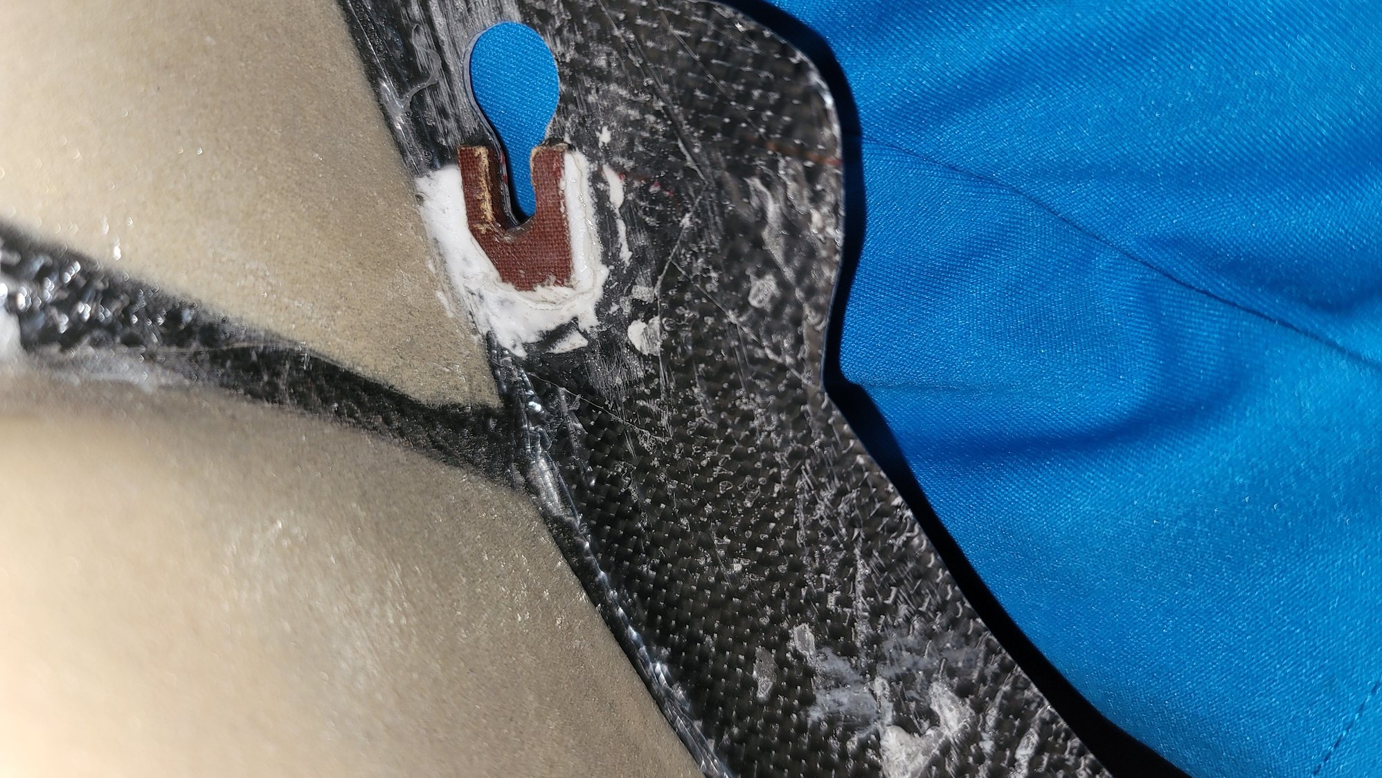
These are the small pieces that "back" the "keyholes" for the rear fuse to join. There is no glue on the face and only around the edges. This is pre-repair
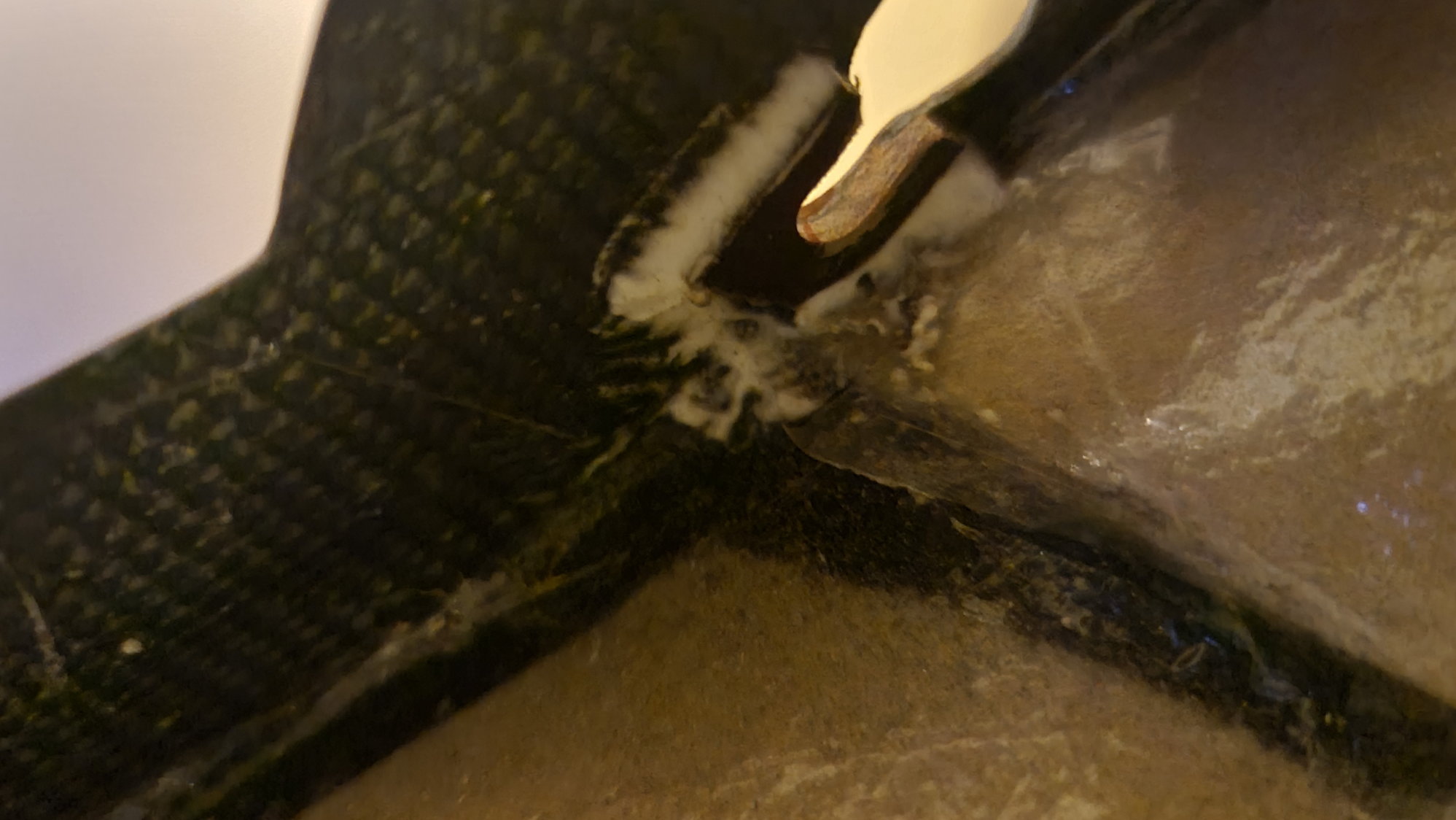
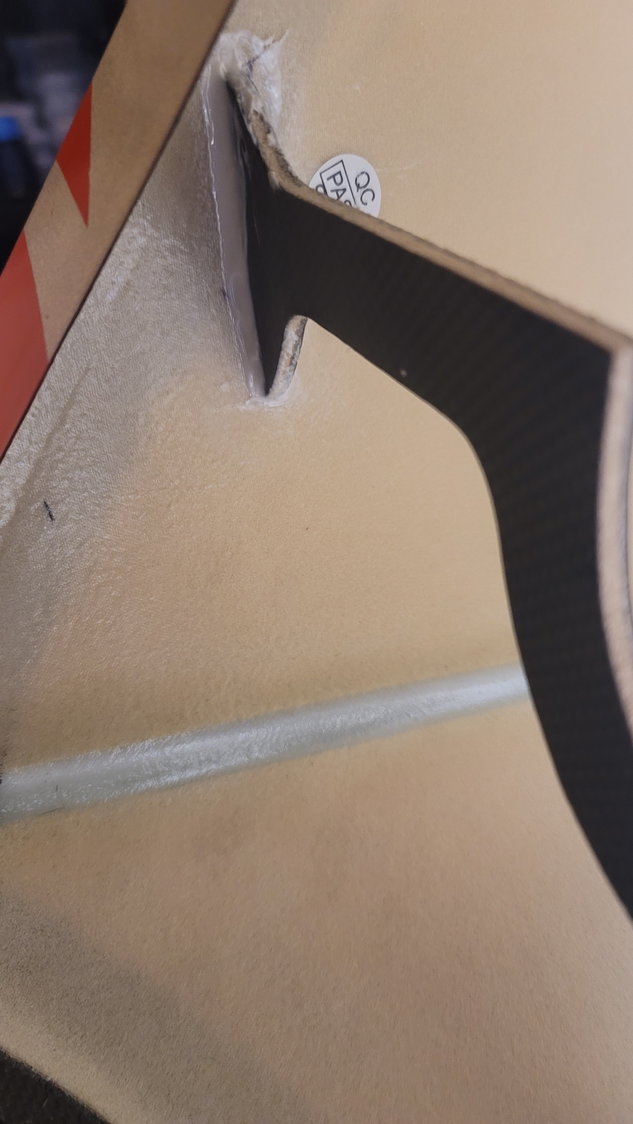
This is after repair with 5-minute epoxy
As big as this jet is, it was extremely helpful to have Dick's help on this. He would sit at the back of the fuse while I adjusted the pipe and former to get it perfectly lined up. As I stated in the previous post, I felt it was necessary to trim a bit off the top of the former (carbon-laminated balsa) to better align the pipe and turbine. Dick agreed. The alignment side to side looked very good with no need for adjustment. We took the fuse back apart and trimmed 1/8" off the top of the former and the brace. You'll want to be fairly diligent in your trim here as the brace is angled so just a straight cut will not work. Additionally, the former is slightly curved so be sure to take your time here to get it right. Once we finished the cut, we reassembled the fuse and lined everything up again with Dick checking the alignment of the tube to turbine. He has such a keen eye for this. When he felt it was right, he asked me to come take a look. Honestly, I have no idea how we did it with just that one trim but the turbine was perfectly centered in the tube.
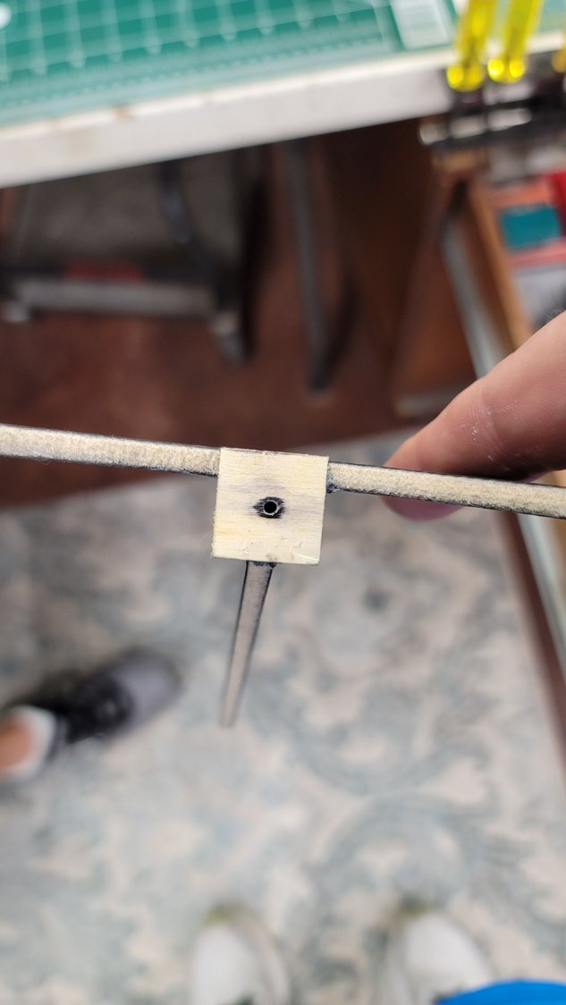
Next, we took a pen and marked the location of the former "arms" that come in contact with the fuse making sure that the former was square to the opening. Then, we marked the front of the little ply block embedded in the former on the pipe and also marked the absolute center of the little block. Remember, this is where the screw will go through the pipe and into that block to hold the pipe in place. Once done, we pulled the fuse apart and removed the former and the pipe again. Now, it's time to drill the hole in the pipe and center the hole on the wood block. Measuring the depth of the block, we marked center and transferred that location on to the pipe (remember we had the line of the front of the block and center already marked on the pipe prior to removal). I used a 7/64" sheet metal screw and washer so we drilled a 1/16" hole in the pipe and then a 1/8" hole. This allows me to put the washer against the head and run the screw from inside the pipe into the plywood piece in the former. Remember, if you don't put the hole in the very top of the tube (re: angled exhaust), the tube's exhaust will sit in the fuselage at an angle. Please pay attention when it's your turn!
We actually drilled this hole with the drill press so that it would go through the ply block and the former. After, we ran CA into the hole and then ran the screw in and out a few times to set the threads.
Once this was complete, we, again, reassembled the fuse with the pipe and the former in it, stood the former up in place and put it at its marks we made and screwed the thrust tube into the former.. Once this was together, we could go back and make absolutely sure the tube and turbine were lined up. Everything was perfect. I was still amazed. From this point, we took CA glue and tacked in the former so that it couldn't move. This is the result:
7/64" sheet metal screw securing the pipe to the former
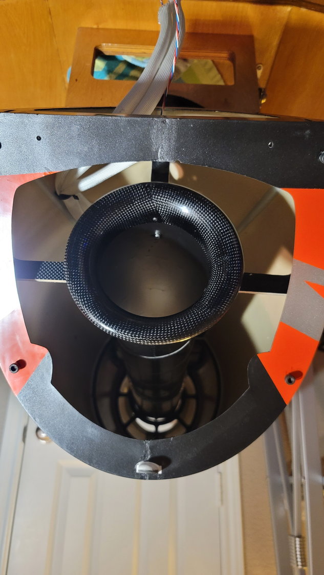
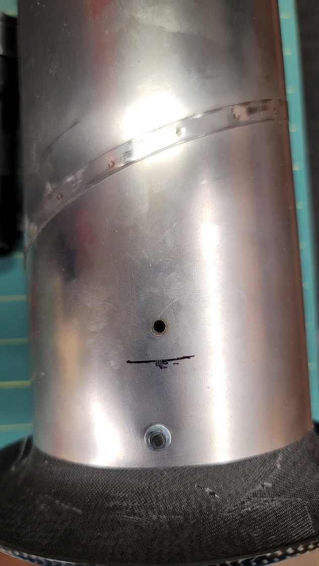
Note that I have not yet set the distance between the turbine and the thrust tube. This isn't that far off, however.
Manual says 10-15mm of tube should be sticking out from the back of the fuse. This is 12mm measured at the bottom.
Tonight or tomorrow night, I'll go ahead and Hysol the former in place. This will complete the aft section of the fuselage. Next, I will mount the turbine and start the placement of the equipment. I think I'll do this prior to the fuel tank if for no other reason than to have more room to run wires and mount equipment (not that there's not enough room in this beast).
Again, a special thanks to Jack for the verbal walk through and some pictures of how he did his and to Dick Mundee who helped me stay sane and on track getting this done properly. Incidentally, these pictures were taken in his workshop which I'm very envious of. We tried to do it at my house but my little work room is pitiful and this jet takes up the entire room. Not to mention, I have just a few lights in there and it is entirely too dim to take that portion on. Thank you sir.
So, last night, I enlisted the help of my buddy Pattratt1 who is a perfectionist when it comes to jets and ways to accomplish things to get them as close to perfect as possible. We live in a fairly small town where Texas A&M is and we are the only two that fly jets in this area. We both usually wind up traveling down to Houston and fly at Bomber Field because our local field isn't really suited for jets. We have no hobby shop and while we have a few very good modelers, no one does jets here. He's become a very good friend to me and we've known each other over a decade. He has my trust.
I told him that I'd like his guidance on permanently mounting and gluing the former in place because it is absolutely necessary to get it set perfectly to align the pipe and the turbine. I've already gone through the steps in my previous post and will just add the nuances here:
First, to explain again how the two fuse halves assemble. There are 4 bolts that are mounted into the aft section. Then there are 4 "keyhole" slits in the front half of the fuse where the heads of the bolts in the rear section slide into and down. On the inside of these keyhole slits, there is a wood back plate to help hold the aft section. I bring this up because, as I said previously, you do have to take the two halves apart a few times to finish the job and you must be somewhat careful when aligning the two halves. What we found during the initial fitting is that one of the wood pieces had come off of the keyhole. This wasn't really surprising to me but, the amount (or should I say lack of amount) of glue was. It's obvious that the little pieces were held up to the keyhole and a very small amount of factory glue was used around the edges. If this is Hysol, it's a weird type. It is almost chalky in nature and easily flaked off the glued wood. There was no glue on the face of the wood or fuse, only around the edges. I can't imagine that the fit would be very good without these little backers/shims so, if I were you, I'd break them away and re-glue them with some 5-minute epoxy properly. It'll be very important to line them up properly but this task is very simple.
These are the small pieces that "back" the "keyholes" for the rear fuse to join. There is no glue on the face and only around the edges. This is pre-repair
This is after repair with 5-minute epoxy
As big as this jet is, it was extremely helpful to have Dick's help on this. He would sit at the back of the fuse while I adjusted the pipe and former to get it perfectly lined up. As I stated in the previous post, I felt it was necessary to trim a bit off the top of the former (carbon-laminated balsa) to better align the pipe and turbine. Dick agreed. The alignment side to side looked very good with no need for adjustment. We took the fuse back apart and trimmed 1/8" off the top of the former and the brace. You'll want to be fairly diligent in your trim here as the brace is angled so just a straight cut will not work. Additionally, the former is slightly curved so be sure to take your time here to get it right. Once we finished the cut, we reassembled the fuse and lined everything up again with Dick checking the alignment of the tube to turbine. He has such a keen eye for this. When he felt it was right, he asked me to come take a look. Honestly, I have no idea how we did it with just that one trim but the turbine was perfectly centered in the tube.
Next, we took a pen and marked the location of the former "arms" that come in contact with the fuse making sure that the former was square to the opening. Then, we marked the front of the little ply block embedded in the former on the pipe and also marked the absolute center of the little block. Remember, this is where the screw will go through the pipe and into that block to hold the pipe in place. Once done, we pulled the fuse apart and removed the former and the pipe again. Now, it's time to drill the hole in the pipe and center the hole on the wood block. Measuring the depth of the block, we marked center and transferred that location on to the pipe (remember we had the line of the front of the block and center already marked on the pipe prior to removal). I used a 7/64" sheet metal screw and washer so we drilled a 1/16" hole in the pipe and then a 1/8" hole. This allows me to put the washer against the head and run the screw from inside the pipe into the plywood piece in the former. Remember, if you don't put the hole in the very top of the tube (re: angled exhaust), the tube's exhaust will sit in the fuselage at an angle. Please pay attention when it's your turn!
We actually drilled this hole with the drill press so that it would go through the ply block and the former. After, we ran CA into the hole and then ran the screw in and out a few times to set the threads.
Once this was complete, we, again, reassembled the fuse with the pipe and the former in it, stood the former up in place and put it at its marks we made and screwed the thrust tube into the former.. Once this was together, we could go back and make absolutely sure the tube and turbine were lined up. Everything was perfect. I was still amazed. From this point, we took CA glue and tacked in the former so that it couldn't move. This is the result:
7/64" sheet metal screw securing the pipe to the former
Note that I have not yet set the distance between the turbine and the thrust tube. This isn't that far off, however.
Manual says 10-15mm of tube should be sticking out from the back of the fuse. This is 12mm measured at the bottom.
Tonight or tomorrow night, I'll go ahead and Hysol the former in place. This will complete the aft section of the fuselage. Next, I will mount the turbine and start the placement of the equipment. I think I'll do this prior to the fuel tank if for no other reason than to have more room to run wires and mount equipment (not that there's not enough room in this beast).
Again, a special thanks to Jack for the verbal walk through and some pictures of how he did his and to Dick Mundee who helped me stay sane and on track getting this done properly. Incidentally, these pictures were taken in his workshop which I'm very envious of. We tried to do it at my house but my little work room is pitiful and this jet takes up the entire room. Not to mention, I have just a few lights in there and it is entirely too dim to take that portion on. Thank you sir.
Last edited by smcharg; 12-10-2021 at 05:31 AM.
The following 2 users liked this post by smcharg:
AEROSHELDON (12-09-2021),
Canadian Man (12-15-2021)
12-09-2021, 10:18 AM
#58
Senior Member
Great work Scott, like how you discussed the procedure and having your friend with another set of eyes is priceless in getting it all aligned up.
I've had issues with Hysol not sticking even with proper cleaning and sanding , most of the glue stuck but some didn't .
In the Rebel pro I'm guessing there will be the same mount bracket I appreciate your post about the issues that can arise.
Great job.
I've had issues with Hysol not sticking even with proper cleaning and sanding , most of the glue stuck but some didn't .
In the Rebel pro I'm guessing there will be the same mount bracket I appreciate your post about the issues that can arise.
Great job.
The following users liked this post:
smcharg (12-09-2021)
12-10-2021, 05:45 AM
#59
Thread Starter
My Feedback: (1)
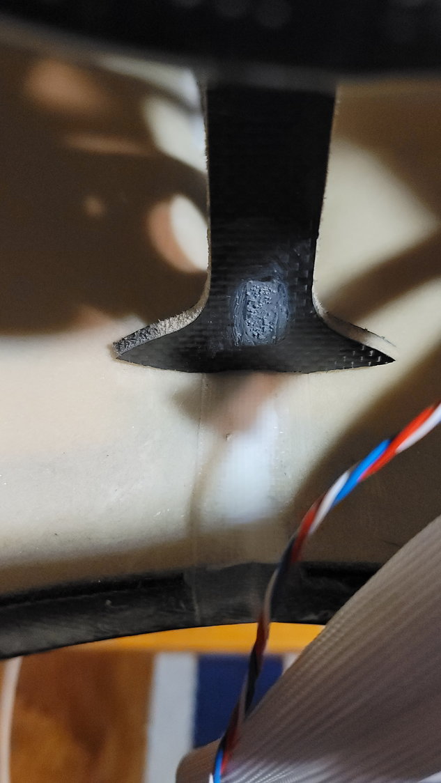
Not much to add from last night's session. I forgot to mention that, in order to achieve the correct amount of pipe sticking out the back of the aircraft, I had to trim away some of the engine rails in order for the bell mouth to clear it. The part trimmed was not structural in that the turbine wouldn't be bolted to this part and it was a cantilevered beam section. I took 10mm out of each side (back to front). We then took the all-encompassing magic that is Mr. Black Sharpie and colored in the cutout portion. It really is amazing how the grain shows through and looks almost natural...from a Sharpie.
10mm in depth, back to front, was removed so that the bell mouth of the thrust tube would not touch the engine rails
Here are some pictures of the thrust tube former all finished without the pipe so you can get a better look. I mixed up a bunch of Hysol 9462 and put it all around the base. I learned something...there are ends that you can put on Hysol tubes that do the mixing for you. Unfortunately, I learned about this after. So, what you are about to see is a result of me mixing the Hysol like we do epoxy on a piece of cardboard and then applying it with a small screwdriver and "smearing" it with my sausage fingers. I cleaned it all up with paper towels after the fact. I'm not bragging about this work, mind you, just merely pointing out there's a better solution (and probably less messy) than the way I did it. Now I know....
The following 2 users liked this post by smcharg:
AEROSHELDON (12-10-2021),
Skunkwrks (12-10-2021)
12-13-2021, 08:36 AM
#60
Thread Starter
My Feedback: (1)
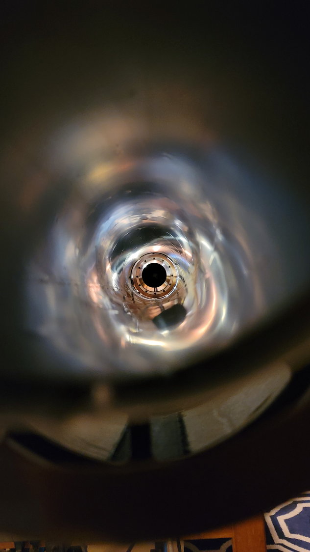
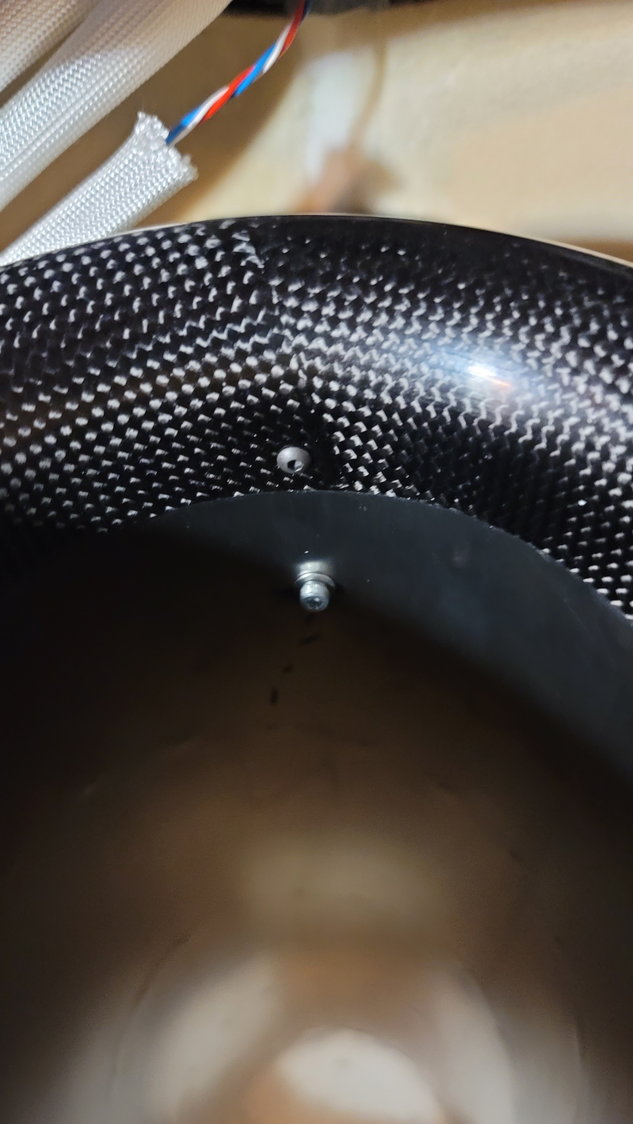
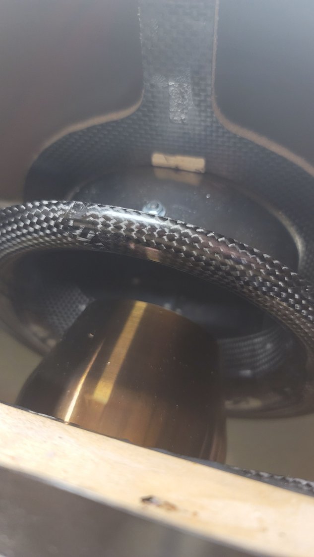
The pipe is now remounted in the aft fuse section and ready to go. The last part of this is mounting the turbine permanently with the right spacing. I used some 6-32 blind nuts/T-nuts and socket head bolts with Locktite. A lot of folks like to use wood screws to mount the turbine. I do not. I know the turbine is going to have to go in and out a few times in its life if for no other reason than sending it back to the manufacturer for 25 hour service. I'd rather have something that is a little more robust than wood screws which is why I use the T-Nuts. Plus, with the bigger turbines, that's a lot of thrust on 4 wood screws. Just my opinion. In the manual that comes with the Max, it's recommended to have 25-30mm spacing between the tip of the exhaust cone and the start of the pipe...not the bell mouth. It's very easy to stick a ruler under the turbine and into the pipe to get your measurements. Mine is at 27mm. Again, take your time to make sure everything is aligned. Top to bottom and side to side. It takes a minute but is easy to do by looking up the pipe to the turbine to line it all up.
6-32 T-nuts and socket head bolts. Use Locktite.
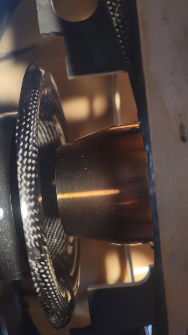
The angle of the picture doesn't really show that the exhaust tip is actually in the bell mouth, but it is just slightly. 27mm from the tip to the start of the pipe. This picture also shows you why I cut off part of the back of the engine mount as explained in the last post.
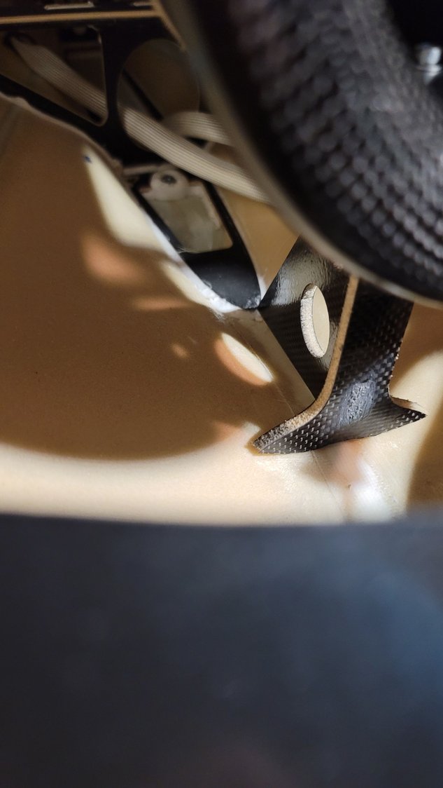
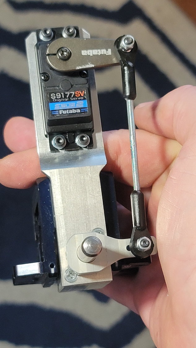
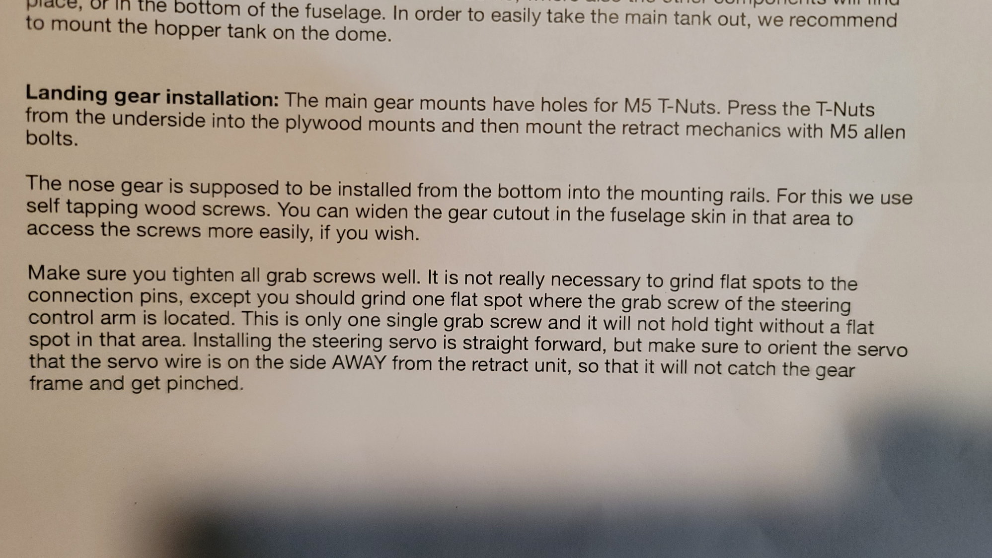
The next part I decided to tackle was installing the Electron ER50evo nose gear retract and steering servo. This, also, is not difficult but does take a little time to do right and common sense. After reading the very short paragraph in the manual about the installation, I understood that the ER50 was meant to be installed from the bottom side of the mounting plate. This is to say that the base of the retract mounts from underneath while the rest of it is up top (Picture to follow here). I placed the main body of the retract where I thought it should go just to get an idea. Of course, you will need to completely assemble the retract with the steering arm and strut to know exactly where it needs to go so this is just a trial fit. The first thing I noticed is that the forward bulkhead has to be trimmed in order to allow clearance for the motor part of the retract. I used my Dremel to grind it out.
The next step will be to assemble the complete nose gear unit. This includes, retract unit, steering servo, steering arm both on the servo and on the strut, linkage, and strut with the wheel. Reading both the manual from CARF and the manual from Electron, they say that you should not grind flat spots into the strut pin for the grub screws. I know Dave says to do it and I do believe him but, I've decided to do what CARF and Electron both say (and I may try it on the mains but still may grind flats into those). Where you do need to grind a flat spot is for the steering arm grub screw. Without this, it will turn under load. Since it doesn't matter exactly where on the arm that you grind the flat spot, I put the strut pin into the assembly and then put the steering arm on the pin and measured the distance from the base of the unit to where the grub screw is in the arm as the arm assembly will sit next to the base. I believe the measurement was 4mm but measure for yourself. I marked that point with a Sharpie and used my Dremel sanding attachment to make the flat spot. Note that it does not take much AT ALL to grind this small spot. Please be careful and don't use pressure. The pin is fairly soft and the weight of the Dremel tool, itself, is more than enough to quickly make the flat spot. Once the flat spot was made, I assembled everything and lined up the servo arm to the steering arm such that they were as parallel as I could get them for now. Be careful of the length of the servo arm you use as 1 1/4" (34mm) will cause you to have to cut out a portion of the gear plate for it to clear as this unit has the servo bracket that articulates with the retract such that the steering assembly is rigid. I like that part. Once all assembled, I put the strut and wheel assembly onto the pin and centered it to clear the sides of the fuse during extension and retract. Note that, for now, I did not put Locktite on the strut. This is intentional until I get the system up and running with the GS-200 controller so that I can line everything up properly and the strut is centered as the controller is centered. Once that's done, I'll go back and take out the grub screws and use Locktite. Additionally, you will have to drill out the servo arm and steering arm to use the CARF provided ball links. I ran out of 1" Futaba aluminum arms so I used one of my 1 1/4" arms and used the first hole and ground off the rest to clear the gear plate when the retract actuated. I used the middle hole on the steering arm as well. If this isn't enough throw, I can always move the ball link to the inside hole on the steering arm.
The next part was to put the assembly in place and determine the final location to bolt in the retract. Again, the short manual says that they just used wood screws to mount it. I'm sure this is fine but, again, I'm not a fan. Even though CARF says to just use wood screws, they do provide T-nuts and screws. As I was looking at the placement, however, it was easy to see that if I used those T-Nuts, I'd have to grind quite a bit of the T-Nut away as the mounting holes for the ER50 are fairly close to the edge of the mounting block. This didn't excite me much either. What I decided to do was to use 8-32 x 1 1/4" socket head bolts with washers and lock nuts. The socket heads and washers sit against the ER50 plate underneath while the lock nuts and washers were up top.
To begin, I placed the Electron bracket where the screws go on TOP of the plate for alignment. This will make it easy to mark the holes from the top for drilling. Using the Electron manual controller, I held the retract unit in place and slowly actuated the gear checking for clearance of the gear, itself, steering arm and servo arm. It's important to get this straight as an arrow so take your time. Once determined, I center punched the holes into the gear mounting plate and drilled a small 1/16" hole in the plate. This would allow me to move the retract plate underneath to make sure everything was still centered and actuate the retract again to check for accuracy. This technique worked very nice and it was easy to do. I then drilled out the holes to the proper size for the 8-32 bolts and simply installed the gear. This turned out very nice and I'm pleased.
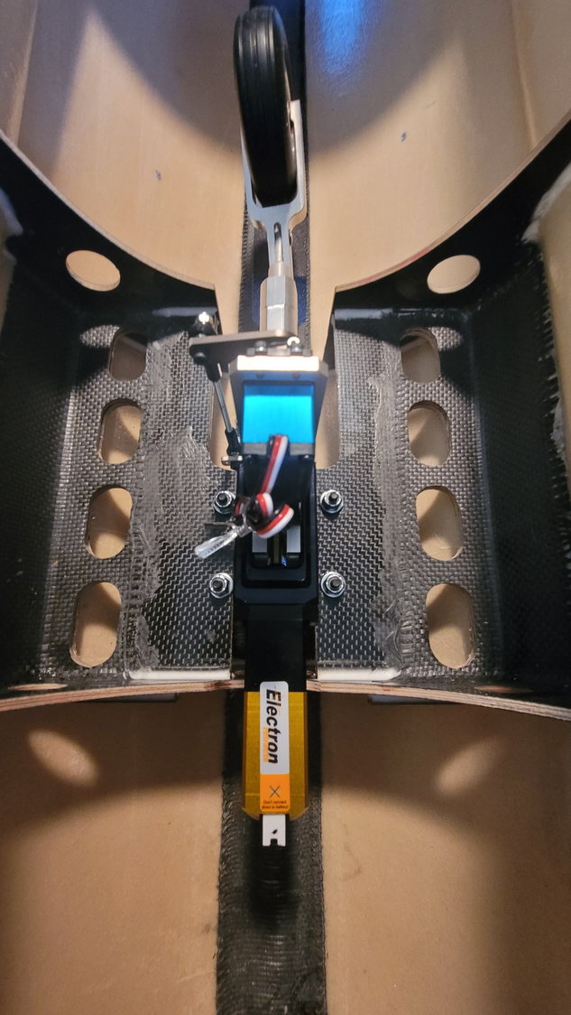
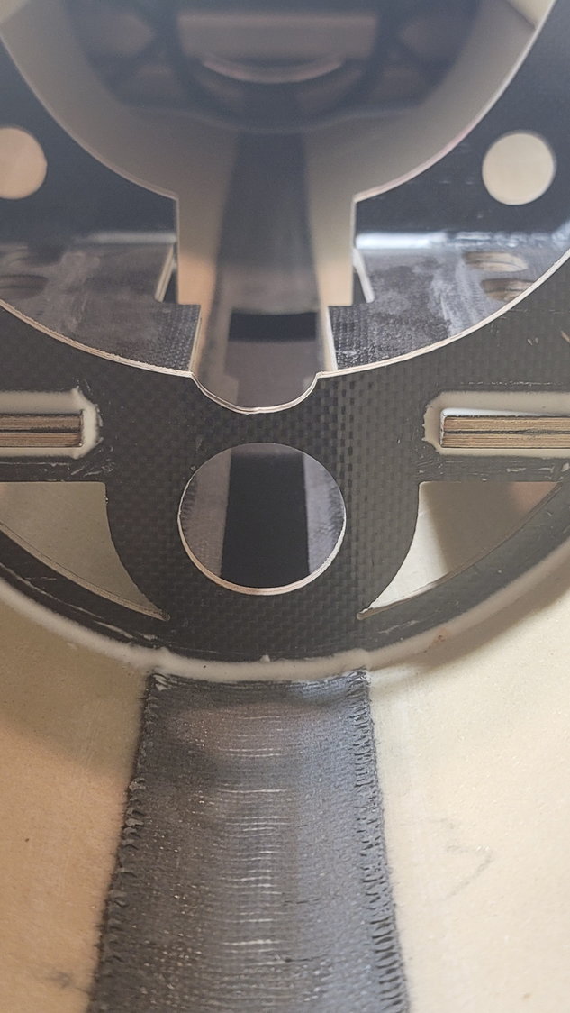
Top View
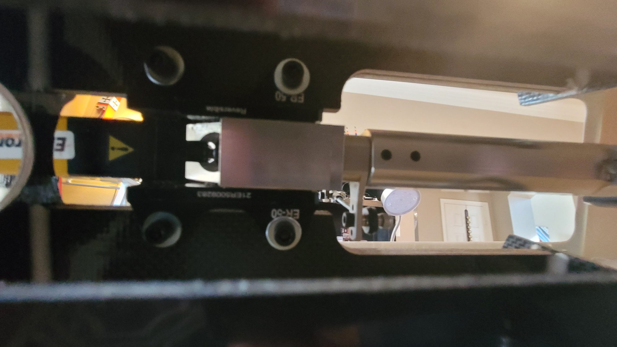
Bottom view
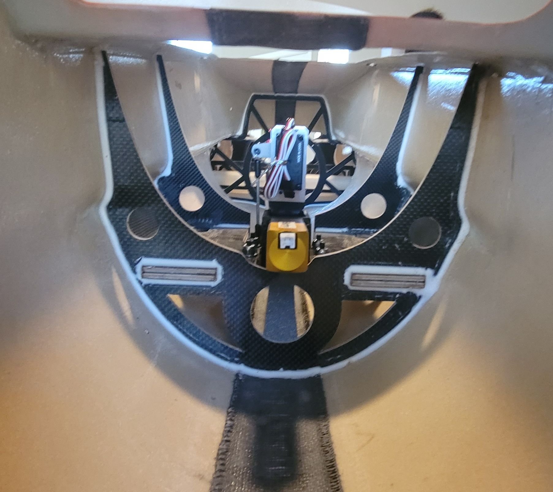
View from front looking back in the fuse
Next, I finally get to start installing avionics equipment. This is my favorite part. I was planning on using the PowerBox Mercury SRS that I have laying around but, I like bling and technical crap. I'm all about UI and appeal. So, yesterday, I decided to order the PowerBox Competition SR2 with the new color display and an iGyro SAT. I'll also use a GPS III sensor from one of my Mercury systems. Is this necessary? Heck no. In fact, the Mercury worked flawlessly in the T-1 and did everything I needed it to do but, as I said,I like cool stuff. The next picture is the TFT display of the Mercury and the following is the display of the Competition SR2 and the entire reason I'm doing it. I'll use the Mercury in something else for sure. Note that the Mercury and the Competition are the same price but what you don't see is that the Mercury already has the iGyro built in so, in actuality, it is cheaper. Yes, it did cost me a little more to do this but this is the biggest, most expensive jet I've ever owned and I want it to be super nice. While I am a Futaba pilot, there are some other features of the Competition SR2 and the Royal that cannot be denied. One of them is if you use the PowerBox Core radio or, I believe, the Jeti radio, you can adjust all the functions from the transmitter. The technology in PowerBox is really amazing and is something for any pilot to consider.

Mercury SRS display
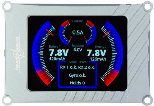
Competition SR2 display
This should arrive this week and I will start laying out components on the top deck of the Max. I've already placed (but haven't bolted down) the DigiTech 250ml UAT on the top of the deck at the rear and I'll start arranging everything else when this unit gets here.
6-32 T-nuts and socket head bolts. Use Locktite.
The angle of the picture doesn't really show that the exhaust tip is actually in the bell mouth, but it is just slightly. 27mm from the tip to the start of the pipe. This picture also shows you why I cut off part of the back of the engine mount as explained in the last post.
The next part I decided to tackle was installing the Electron ER50evo nose gear retract and steering servo. This, also, is not difficult but does take a little time to do right and common sense. After reading the very short paragraph in the manual about the installation, I understood that the ER50 was meant to be installed from the bottom side of the mounting plate. This is to say that the base of the retract mounts from underneath while the rest of it is up top (Picture to follow here). I placed the main body of the retract where I thought it should go just to get an idea. Of course, you will need to completely assemble the retract with the steering arm and strut to know exactly where it needs to go so this is just a trial fit. The first thing I noticed is that the forward bulkhead has to be trimmed in order to allow clearance for the motor part of the retract. I used my Dremel to grind it out.
The next step will be to assemble the complete nose gear unit. This includes, retract unit, steering servo, steering arm both on the servo and on the strut, linkage, and strut with the wheel. Reading both the manual from CARF and the manual from Electron, they say that you should not grind flat spots into the strut pin for the grub screws. I know Dave says to do it and I do believe him but, I've decided to do what CARF and Electron both say (and I may try it on the mains but still may grind flats into those). Where you do need to grind a flat spot is for the steering arm grub screw. Without this, it will turn under load. Since it doesn't matter exactly where on the arm that you grind the flat spot, I put the strut pin into the assembly and then put the steering arm on the pin and measured the distance from the base of the unit to where the grub screw is in the arm as the arm assembly will sit next to the base. I believe the measurement was 4mm but measure for yourself. I marked that point with a Sharpie and used my Dremel sanding attachment to make the flat spot. Note that it does not take much AT ALL to grind this small spot. Please be careful and don't use pressure. The pin is fairly soft and the weight of the Dremel tool, itself, is more than enough to quickly make the flat spot. Once the flat spot was made, I assembled everything and lined up the servo arm to the steering arm such that they were as parallel as I could get them for now. Be careful of the length of the servo arm you use as 1 1/4" (34mm) will cause you to have to cut out a portion of the gear plate for it to clear as this unit has the servo bracket that articulates with the retract such that the steering assembly is rigid. I like that part. Once all assembled, I put the strut and wheel assembly onto the pin and centered it to clear the sides of the fuse during extension and retract. Note that, for now, I did not put Locktite on the strut. This is intentional until I get the system up and running with the GS-200 controller so that I can line everything up properly and the strut is centered as the controller is centered. Once that's done, I'll go back and take out the grub screws and use Locktite. Additionally, you will have to drill out the servo arm and steering arm to use the CARF provided ball links. I ran out of 1" Futaba aluminum arms so I used one of my 1 1/4" arms and used the first hole and ground off the rest to clear the gear plate when the retract actuated. I used the middle hole on the steering arm as well. If this isn't enough throw, I can always move the ball link to the inside hole on the steering arm.
The next part was to put the assembly in place and determine the final location to bolt in the retract. Again, the short manual says that they just used wood screws to mount it. I'm sure this is fine but, again, I'm not a fan. Even though CARF says to just use wood screws, they do provide T-nuts and screws. As I was looking at the placement, however, it was easy to see that if I used those T-Nuts, I'd have to grind quite a bit of the T-Nut away as the mounting holes for the ER50 are fairly close to the edge of the mounting block. This didn't excite me much either. What I decided to do was to use 8-32 x 1 1/4" socket head bolts with washers and lock nuts. The socket heads and washers sit against the ER50 plate underneath while the lock nuts and washers were up top.
To begin, I placed the Electron bracket where the screws go on TOP of the plate for alignment. This will make it easy to mark the holes from the top for drilling. Using the Electron manual controller, I held the retract unit in place and slowly actuated the gear checking for clearance of the gear, itself, steering arm and servo arm. It's important to get this straight as an arrow so take your time. Once determined, I center punched the holes into the gear mounting plate and drilled a small 1/16" hole in the plate. This would allow me to move the retract plate underneath to make sure everything was still centered and actuate the retract again to check for accuracy. This technique worked very nice and it was easy to do. I then drilled out the holes to the proper size for the 8-32 bolts and simply installed the gear. This turned out very nice and I'm pleased.
Top View
Bottom view
View from front looking back in the fuse
Next, I finally get to start installing avionics equipment. This is my favorite part. I was planning on using the PowerBox Mercury SRS that I have laying around but, I like bling and technical crap. I'm all about UI and appeal. So, yesterday, I decided to order the PowerBox Competition SR2 with the new color display and an iGyro SAT. I'll also use a GPS III sensor from one of my Mercury systems. Is this necessary? Heck no. In fact, the Mercury worked flawlessly in the T-1 and did everything I needed it to do but, as I said,I like cool stuff. The next picture is the TFT display of the Mercury and the following is the display of the Competition SR2 and the entire reason I'm doing it. I'll use the Mercury in something else for sure. Note that the Mercury and the Competition are the same price but what you don't see is that the Mercury already has the iGyro built in so, in actuality, it is cheaper. Yes, it did cost me a little more to do this but this is the biggest, most expensive jet I've ever owned and I want it to be super nice. While I am a Futaba pilot, there are some other features of the Competition SR2 and the Royal that cannot be denied. One of them is if you use the PowerBox Core radio or, I believe, the Jeti radio, you can adjust all the functions from the transmitter. The technology in PowerBox is really amazing and is something for any pilot to consider.
Mercury SRS display
Competition SR2 display
This should arrive this week and I will start laying out components on the top deck of the Max. I've already placed (but haven't bolted down) the DigiTech 250ml UAT on the top of the deck at the rear and I'll start arranging everything else when this unit gets here.
Last edited by smcharg; 12-13-2021 at 08:43 AM.
 12-14-2021, 12:16 PM
#62
Senior Member
You need to flat spot both the upper and lower parts of the pins; if not, It will love funny when you steer it, and the planes go in a different direction.
12-14-2021, 12:23 PM
#63
Thread Starter
My Feedback: (1)
I definitely hear y'all and watched Jonathan do exactly that on the Huracan yesterday. I have to wonder, why would both Electron and CARF say you don't "need" to though. Totally not trying to be smart to either of you and I know Dansy does a lot of building and respect what he says. I just don't understand the disparity between manufacturer and "us". I will go back and do all 3 gear though once I finish the build and do the alignment the way Dave said and Jonathan said in his build of the Huracan.
12-14-2021, 12:55 PM
#64

I have this same dilemmma Scott. The users in the field say to flat spot yet the mfr and CARF say it is OK not to? I assume CARF runs a lot of models and tests and if they have issues they would say to flat spot.
I am going to try my Meohisto without (next year, flying season is about over) and see what happens. I'll probably have to flat spot them but they are installed now and I don't want to pull them unless I need to.
I am going to try my Meohisto without (next year, flying season is about over) and see what happens. I'll probably have to flat spot them but they are installed now and I don't want to pull them unless I need to.
The following users liked this post:
smcharg (12-14-2021)
12-14-2021, 03:08 PM
#65
Electron can’t do pins for every model, it’s an impossible situation. Small angular differences on mounting the unit would change the wheel angle and every model design these pins/units are fitted to will vary a little. Imagine the spares stock situation!!!
You might get away with it and as you say CARF do a lot of flying, but how the brakes are set and used will change the forces these pins get, Loctite Used and maybe even the fact that many of CARF’s display models originate from Thailand where heat/moisture might even get the steel pin/alloy leg to chemically ‘rust’ together.
I’m sorry if you cannot grind a few flats on a pin…knitting is an option? 😉
Just do it, if you hit a hole or ridge on take off and the gear twist ‘sods law’ says it will retract into position, but jam coming down and mean you scratch/wreck your shined toy…it is not worth the risk.
The following users liked this post:
Skunkwrks (12-14-2021)
12-14-2021, 04:59 PM
#67

My Feedback: (53)

I definitely hear y'all and watched Jonathan do exactly that on the Huracan yesterday. I have to wonder, why would both Electron and CARF say you don't "need" to though. Totally not trying to be smart to either of you and I know Dansy does a lot of building and respect what he says. I just don't understand the disparity between manufacturer and "us". I will go back and do all 3 gear though once I finish the build and do the alignment the way Dave said and Jonathan said in his build of the Huracan.

This pass season I have seen a Havoc SS (not mine or build) twisted one main on pavement�..he broke the wing to surface and the whole plate�.the force can be that bad�the wheel when sideway�that was on his number 2 flights. He did land a little fast�and only had about 5000� of runway remaining� 🤷🏻♂️
12-14-2021, 05:08 PM
#68

To flat-spot the leg pins or not is probably influenced by if you fly mainly from grass or a hard surface. Landing on a hard surface needs much more brake application than on grass, where brakes are probably not even needed to come to a stop in a reasonable distance.
With the wheel offset from the leg on most gear, braking generates a significant torque on the leg.
I used one flat-spot per leg (Electron) with my Ultra Flash but would occasionally still experience a twisted leg for no apparent reason. 2 flat-spots seems to stop that happening.
Paul
With the wheel offset from the leg on most gear, braking generates a significant torque on the leg.
I used one flat-spot per leg (Electron) with my Ultra Flash but would occasionally still experience a twisted leg for no apparent reason. 2 flat-spots seems to stop that happening.
Paul
The following users liked this post:
smcharg (12-15-2021)
12-14-2021, 09:18 PM
#69
Senior Member
I have this same dilemmma Scott. The users in the field say to flat spot yet the mfr and CARF say it is OK not to? I assume CARF runs a lot of models and tests and if they have issues they would say to flat spot.
I am going to try my Meohisto without (next year, flying season is about over) and see what happens. I'll probably have to flat spot them but they are installed now and I don't want to pull them unless I need to.
I am going to try my Meohisto without (next year, flying season is about over) and see what happens. I'll probably have to flat spot them but they are installed now and I don't want to pull them unless I need to.
Don't know if you fly grass or asphalt the strut will spin on the stud.
Just like Dave said "just do it, or take up knitting" Lol is part of the assembly sequence of these jets.
I would hate to f up that Mephisto over something so easy to do, parts take six months to arrive from the factory.
The following users liked this post:
AEROSHELDON (12-15-2021)
12-14-2021, 09:59 PM
#70
As said the forces possible to twist the leg are incredible. These are from the shock type rather than pure twisting, A hammer rested on a nail, a hammer dropped onto a nail with gravity and a hammer smashed down onto the nail…it multiplies
Set screws have always been an interesting one for me, I see people tightening U/C set screws with an Allen driver…sometimes ball ended!!
No no no. Break out my Bondhus Gorilla set of L Allen Keys and ‘give it some ‘
If you don’t own a set there is a perfect Xmas gift for you from the ‘Knitter’ 😊
Set screws have always been an interesting one for me, I see people tightening U/C set screws with an Allen driver…sometimes ball ended!!
No no no. Break out my Bondhus Gorilla set of L Allen Keys and ‘give it some ‘
If you don’t own a set there is a perfect Xmas gift for you from the ‘Knitter’ 😊
12-15-2021, 05:52 AM
#71
Thread Starter
My Feedback: (1)
Dave Wilshere
I think my point isn't to do it or not...y'all have made your points and they are taken to heart. In reality, it's not that this is a hard task to complete aside from maybe having to heat up the pin to get it out of the part opposite the strut so, certainly, it's not the work involved. The reason I started this thread was to help the newb who gets a small 4 page "Short Manual" and minimal directions from CARF and isn't that much of a builder nor has the people/resources to help him/her. This is the reason for my long posts as I'm trying to explain everything I go through.
My point is that the manual says you shouldn't have to. As a rep for CARF, I'd think you'd want to help Andreas correct the manual if you're that steadfast on the need to do it. If not you, maybe another rep. The informed and skilled folks such as yourself and others know to grind the flat spots and the reasoning behind it. It 100% all makes sense and, hopefully, common sense will prevail. All you're trying to do is save someone's airplane. I applaud you for doing so and helping all of us whether we're in your area or not. That is the sign of someone who really cares and I appreciate it. I think that my goal here was to point out that CARF is saying don't and those that know say do. It also makes sense that Electron doesn't flat spot the pins for you. As you say, this would be impossible and I would not expect them to do so. But, they also say you shouldn't have to. It's the fact that they are saying don't need to but it's obvious we do.
The following users liked this post:
Canadian Man (12-15-2021)
12-15-2021, 07:48 AM
#72
Thread Starter
My Feedback: (1)

The following users liked this post:
smcharg (12-15-2021)
12-15-2021, 10:35 AM
#74
Also Dave Wilshere , are these the allen wrenches you like? I searched for Bondhus Gorilla.....
https://www.amazon.com/Bondhus-12533...9583152&sr=8-1
https://www.amazon.com/Bondhus-12533...9583152&sr=8-1
I�m a German Wiha tool fan of everything except their Allen L keys. Bondhus are the daddy when it comes to them. I do have a set of short leg L keys from Wiha, they have less offset to twist when you fully tighten something.
You cannot have enough tools, I�m in the thousands 🙂