


M60a3 DKLM kit build
 09-09-2018, 08:05 PM
#1

Thread Starter

Ugh, no idea why the first picture came out vertical, they are all landscape on my pc and how I took them...
Ok so I have finally started building my kit now that I am back on track with the daily grind.
I have the manual although its the foreign language one, so I just have pictures to go from.
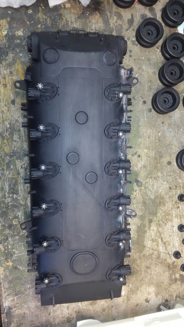
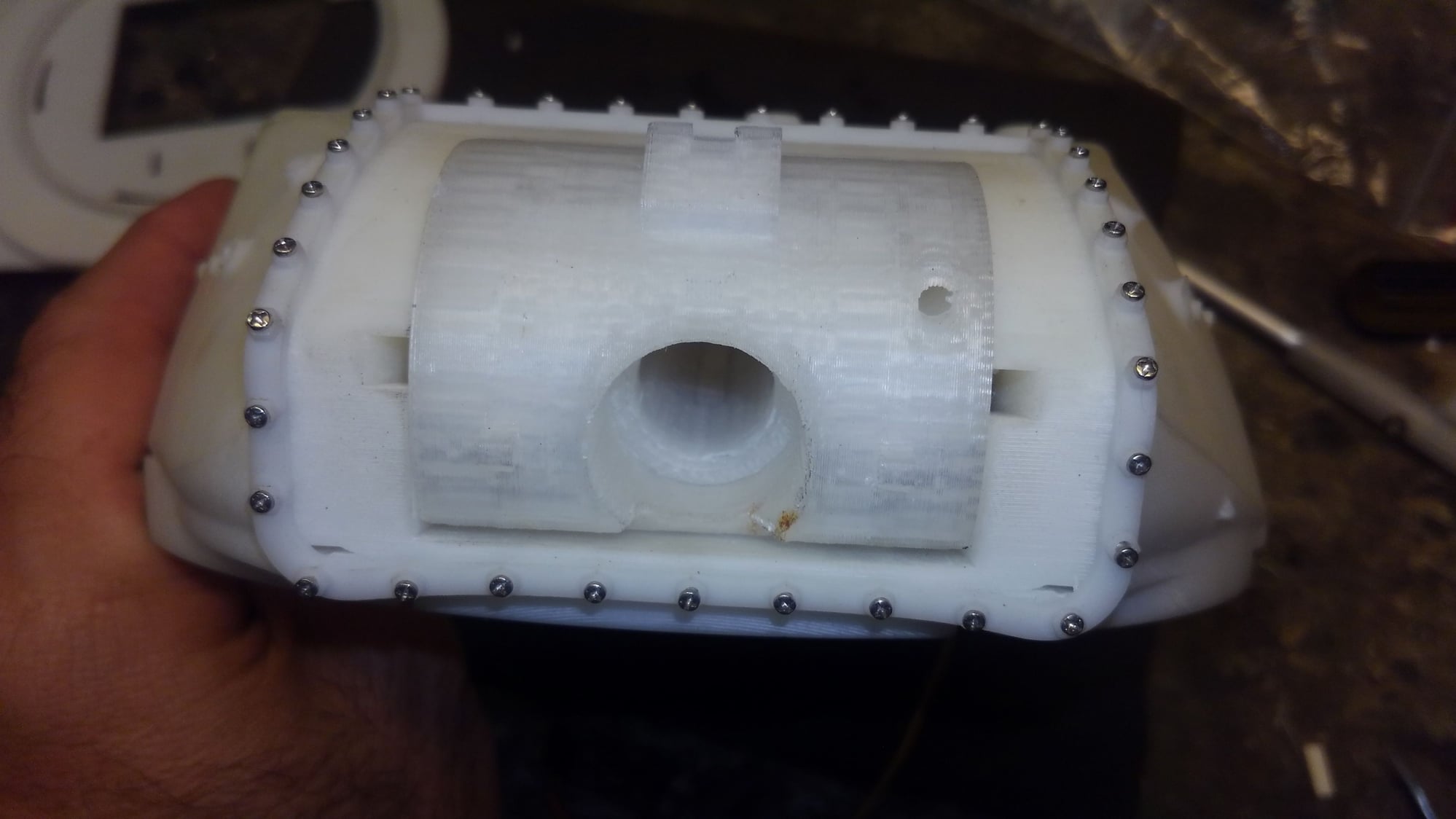
As seen below the short screws go in the bottom to hold the torsion bar locks in place.
The hull print job is really good. Not quite as nice as the turret and upper hull though. There were some grooves in the upper concave area on one side that I felt I just had to fill in with putty and there was print texture along the bottom curve on the opposite side around the trailing arm mounts and all the stops etc. That was a lot more work to sand with sticks and sheet paper and then go back and fill in. It wasn't really too bad, nothing like shapeways, but for the quality of this kit and the effort and cost, I am a perfectionist so to make myself happy I went for all the work.
Inside, I did not receive screws for the gear boxes to screw them into the hull, or the proper screws to lock down the torsion bars. I did receive two sets of long screws and washers for the wheels which are the same size and I was going to use them, but sitting in my screw cup on the bench was all the screws from tearing apart a Tamiya Sherman speaker. The metric M3(I think) machine screws fit the bill for the torsion bar locks and the plastic course thread screws were perfect for the gear box mounting. Although a tad long so I just drilled the holes about 1-2mm deeper.

I started on the turret. These two screws are long and they go vertically into the rear mantlet area to retain the rotor shield in the turret from the front. They are nasty tight and I nearly have one stripped now getting it in. The holes should be tapped with I think a 3mm tap. I may still go back and do that. Also, you must cut a notch out of the turret floor to fit around each of the two retainer screw heads as seen in my photo.
This is all stuff I figured out so far from this build. I hope I am not missing anything else in the kit.
I upgraded and went and found metal pershing wheels with bearings and tires along with metal sprockets, metal high speed rotation box and metal track.
I started priming the wheels and all the trailing arms and shocks etc today as well.

Ok so I have finally started building my kit now that I am back on track with the daily grind.
I have the manual although its the foreign language one, so I just have pictures to go from.
As seen below the short screws go in the bottom to hold the torsion bar locks in place.
The hull print job is really good. Not quite as nice as the turret and upper hull though. There were some grooves in the upper concave area on one side that I felt I just had to fill in with putty and there was print texture along the bottom curve on the opposite side around the trailing arm mounts and all the stops etc. That was a lot more work to sand with sticks and sheet paper and then go back and fill in. It wasn't really too bad, nothing like shapeways, but for the quality of this kit and the effort and cost, I am a perfectionist so to make myself happy I went for all the work.
Inside, I did not receive screws for the gear boxes to screw them into the hull, or the proper screws to lock down the torsion bars. I did receive two sets of long screws and washers for the wheels which are the same size and I was going to use them, but sitting in my screw cup on the bench was all the screws from tearing apart a Tamiya Sherman speaker. The metric M3(I think) machine screws fit the bill for the torsion bar locks and the plastic course thread screws were perfect for the gear box mounting. Although a tad long so I just drilled the holes about 1-2mm deeper.
I started on the turret. These two screws are long and they go vertically into the rear mantlet area to retain the rotor shield in the turret from the front. They are nasty tight and I nearly have one stripped now getting it in. The holes should be tapped with I think a 3mm tap. I may still go back and do that. Also, you must cut a notch out of the turret floor to fit around each of the two retainer screw heads as seen in my photo.
This is all stuff I figured out so far from this build. I hope I am not missing anything else in the kit.
I upgraded and went and found metal pershing wheels with bearings and tires along with metal sprockets, metal high speed rotation box and metal track.
I started priming the wheels and all the trailing arms and shocks etc today as well.
 09-10-2018, 12:15 PM
#2

You got instructions? Lucky bar steward. Lol.
Yeah, I noticed the holes for the screws holding the trunnions in the turret are really tight. I stopped until I can dig out my taps. Kind of on hold here anyway, getting ready for the new baby.
Yeah, I noticed the holes for the screws holding the trunnions in the turret are really tight. I stopped until I can dig out my taps. Kind of on hold here anyway, getting ready for the new baby.
09-11-2018, 10:34 AM
#3
Thanks Rich.
So, looks like we both got shorted on screws. They all seem to be M3, so it's not that much of a problem.
And now I know what that odd linkage is for. Never thought about it being for the cupola mg elevation.
So, looks like we both got shorted on screws. They all seem to be M3, so it's not that much of a problem.
And now I know what that odd linkage is for. Never thought about it being for the cupola mg elevation.
09-12-2018, 06:33 AM
#4
Thread Starter
Ive installed the gear boxes. I used taigen 3.1 with 390s since I prefer the 39:1 ratio of them over the lower geared mato 69:1 transmissions. I think I will also use a 7 or 8 cell pack in this tank to achieve a good top end speed out of it.
I had to notch the hull side at the top a little bit to clear the side screw for the top shaft of the transmssion. No big deal. The hull is plenty thick enough to do this. I am sure I will be quite happy with these.
I also got all the trailing arms mounted with the torsion bars. I need next to mount the shocks and the front compensating idler. Then the lower hull will be done.
09-13-2018, 10:06 PM
#5
Thread Starter
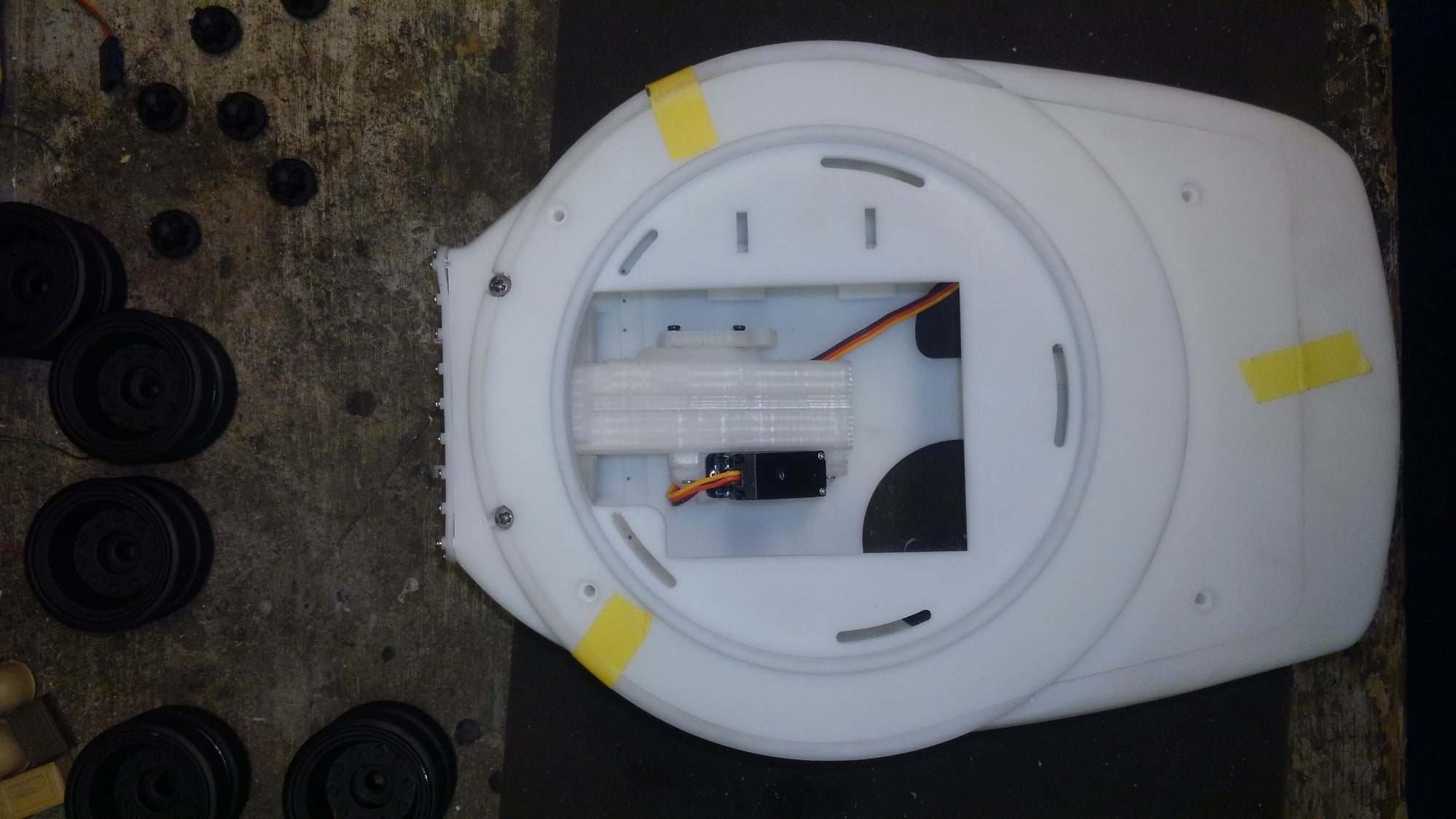
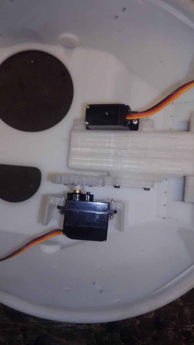
I got some work started on the turret. Installed the rotor shield and elevation servo with the recoil mount.
I found the set up for the elevation servo gear didn't mate well with the cog on the gun breech recoil unit so I turned the servo horn circle inside out and moved the servo to the other side of the stand up brackets to get alignment better. Also found the rotor shield wobbled side to side with a bit of play losing mesh on the elevation gear.
So I lowered the two vertical screws that hold the rotor shield in and cut little .020 plastic shims and jus dropped them in front of the tabs and pushed them in tight with a paint brush stick and screwed the retaining screws up and it worked perfectly. The rotor shield gun mount now stays in place perfectly without play.
I also found I am missing a bunch of other screws DKLM is now sending me.
09-16-2018, 07:43 AM
#6
Thread Starter
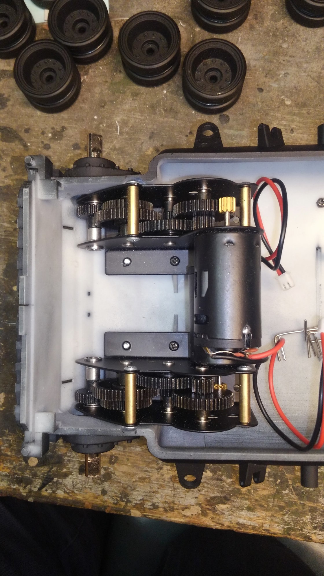
I got an m3 tap and tapped all the wheel screw and roller holes, and the various turret bottom plate screw holes etc. Didn't want to force the screws in like I had to with the rotor shield retaining screws. I used lock tite on the screws for the return rollers since they are shorter and hand rolling the rollers the screws would partially turn. Also I had to drill out the outside wheel of the henglong return rollers to fit over the head of the screw so it would roll freely without grabbing the screw head and turning it. Shown in the picture below. I do have metal return rollers from the wheel kit I bought but a friend told me that the plastic return rollers roll better than the metal ones so I am going to go with them first and test out the tank.
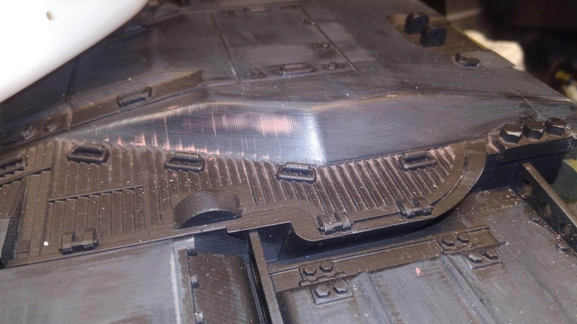
Got the lower hull painted with a color coat. I can see a few more areas now that have grainy line texture from printing that I should have sanded but I going to let it go. Too far now to go back and re do it when it wont be seen unless you handle the tank.
I have about 6 or 8 coats of black primer on the upper hull deck. It has a wider line pattern from printing that can be seen in the right shade of light angle or when the paint is wet.
I wish the upper hull had been printed plain, and required all the details and tool boxes added to it so that it could be sanded smooth and finished nicely. Now I am going to have to sand the rear and front areas around the detail, especially the headlight assemblies to get a perfectly smooth finish to paint it with color. HAving the hull with all the details printed on it saves a lot of time if you don't care about the finish of it. Kinda sad. Now it takes more work to sand around all that suff and make it look good.
Also found that the metal abrams sprocket I bought doesn't fit on the taigen gear box shafts lol. Had to run the gear box full speed at 12v with a model train power pack and use a file to turn down the shaft diameter a few thousandths to get the sprocket to fit lol. Im hoping to be able to test drive the chassis soon with the IBU shows up. Then I can start setting up the recoil etc and move further with the turret internals.
09-16-2018, 07:24 PM
#7
Join Date: Nov 2010
Location: HamiltonWaikato, NEW ZEALAND
Posts: 937
Likes: 0
Received 78 Likes
on
55 Posts
Hi Rich
It's looking good. You might like to try What A Job on the hull - liquid Polymer - I'ved used it on my M41's, M26 & Centurion - fills the gaps, add textures & protection - Environmentally Friendly Water Based Protective Coatings, Paints, Sealers - Industrial, Marine, Roofing ,Construction, Residential and Automotive Industry - I use the Industrial, Smooth, Black sample.
As a Shermanaholic were you aware of this - Armorama :: Circumcised Sherman -
Mal
09-16-2018, 09:22 PM
#8
Thread Starter
AFV Aficionado, I was not. I general use body putty and a scrubby sponge to do cast texture.
At this point Im not going back and doing anything to the lower hull. I have bigger problems to deal with as described below.
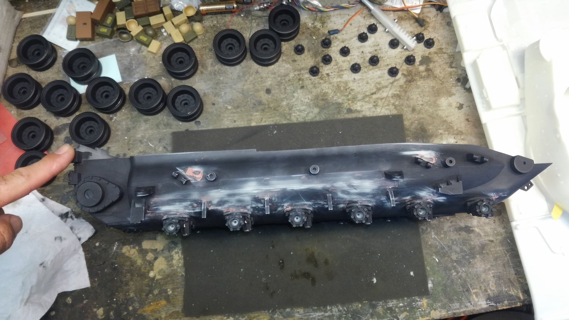
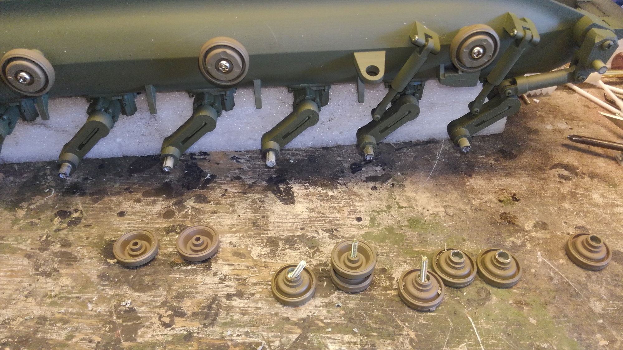
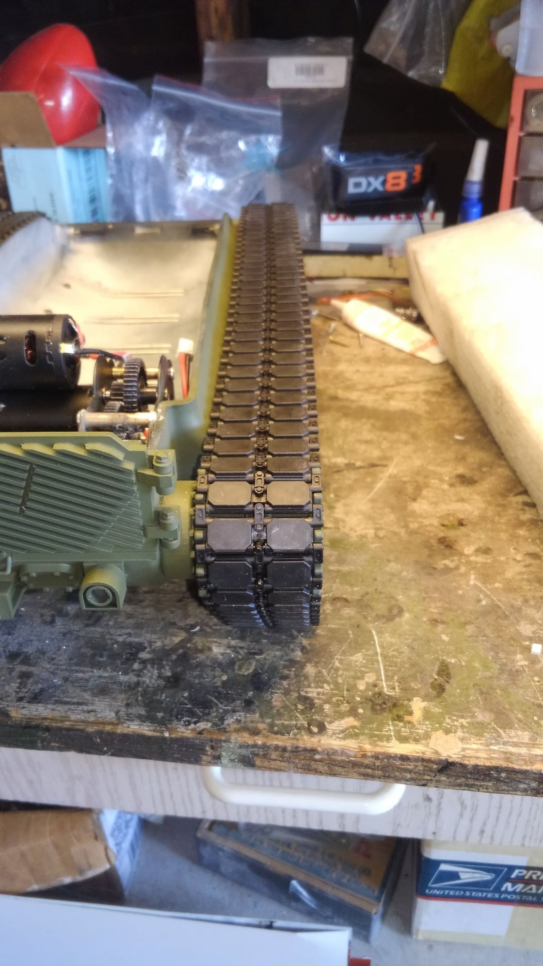
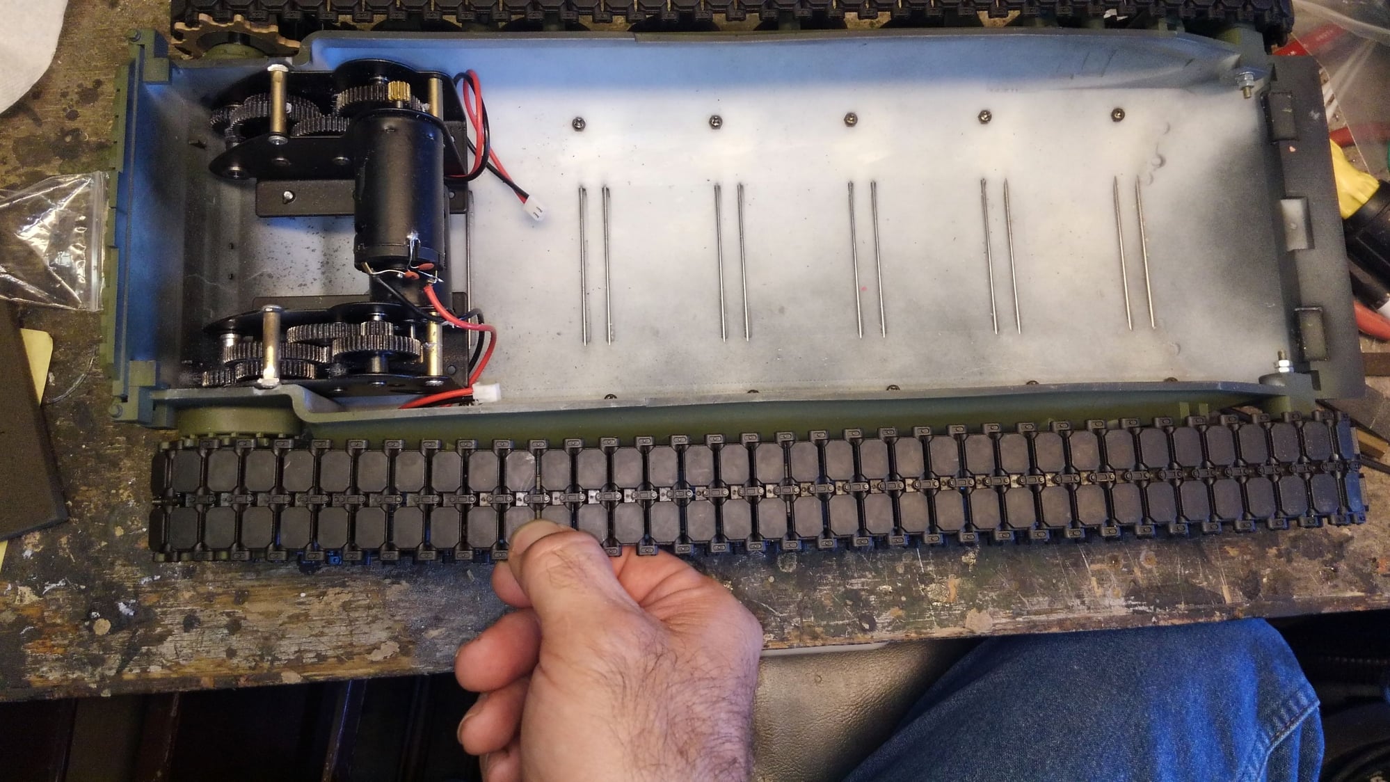
I put the sprockets and track on and found that the sprockets are in toward the hull much further than the road wheels and return rollers. As is, 3 end connectors of track rub the hull pretty good at the back top.
I set a plastic abrams sprocket on the left side and spaced it by eye so that the track would be straight all the way back and I found that I have to move the sprockets 7mm out from the position that they are in right now using the 58mm taigen trannys. I have no explanation as to how DKLM missed this massive flaw other than to say, looking at the photos and video their prototype models show the sprockets further out, probably something to do with the shaft length of their cross drive transmission. The kit came with 58mm mato trannys and I put in 58mm taigen trannys. I don't think they have any trannys that are longer than that do they? Well I came to the conclusion that I need 65mm trannys to make the track line up perfect.
In the picture with my finger on the track I was holding the track in alignment in the rear return roller to demonstrate the extreme angle that the track went inward to the sprocket.
I did refer all this information back to DKLM. I do not understand how they sold this kit with 58mm gear boxes if this is how they line up. There is no way this tank will run with these gear boxes as is. They shafts need to be about 65mm according to my measurements. I suspect they either never built one with the mato gear boxes, or ..... I wont go any further here.
Any way, the only solution is to make longer shafts or discuss buying the cross drive transmission which I don't care for the operational characteristics of.
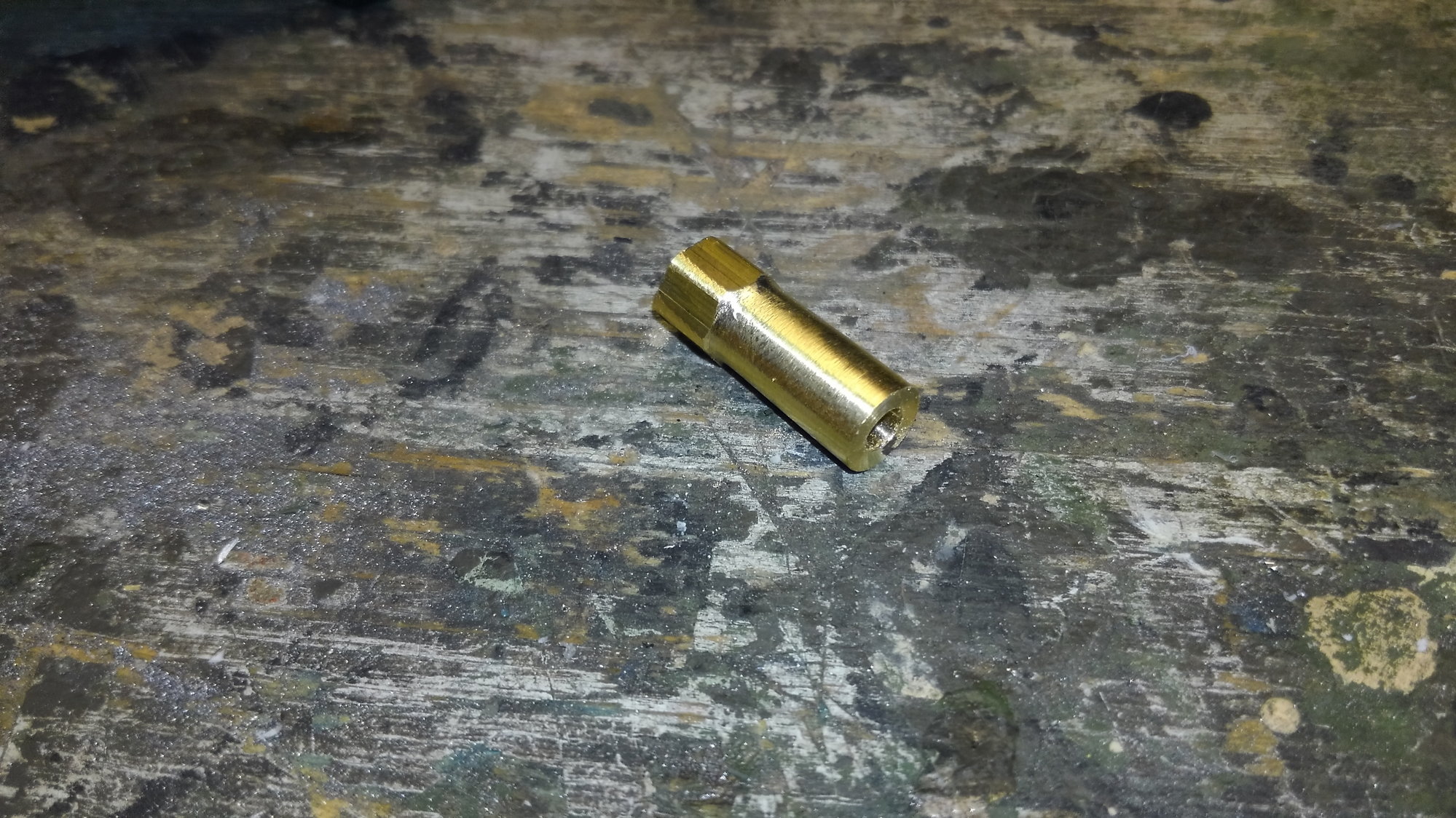
This is the tan plastic abrams sprocket I used to eyeball and then measure the distance I needed to move the sprocket out from the hub.
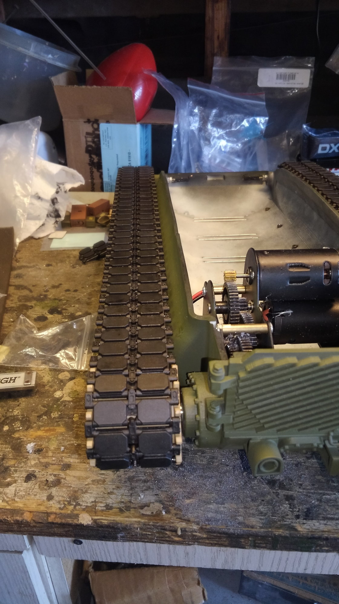
So the solution is to extend the drive shaft length. I got some solid hex stock that was 7.65mm wide on the flat side dia. and cut it and chucked it in my unimat lathe and bore it out to the dia. of the sprocket screw. Then I turned it down to the shaft dia which is about 7.6mm ish and then cut the sections to 7mm long and then screwed them to the end of the taigen steel shaft and then used a mini torch and silver soldered them in place. I then filed the flat spot down and then ran the tranny and trued up the mating diameter so the sprocket would go on nice. Lots of crazy work I had not anticipated and fankly should not have had to do. If anybody buys this kit now I suggest just buy their damn cross drive tranny and live with it or learn to be a amateur machinist.

At this point Im not going back and doing anything to the lower hull. I have bigger problems to deal with as described below.
I put the sprockets and track on and found that the sprockets are in toward the hull much further than the road wheels and return rollers. As is, 3 end connectors of track rub the hull pretty good at the back top.
I set a plastic abrams sprocket on the left side and spaced it by eye so that the track would be straight all the way back and I found that I have to move the sprockets 7mm out from the position that they are in right now using the 58mm taigen trannys. I have no explanation as to how DKLM missed this massive flaw other than to say, looking at the photos and video their prototype models show the sprockets further out, probably something to do with the shaft length of their cross drive transmission. The kit came with 58mm mato trannys and I put in 58mm taigen trannys. I don't think they have any trannys that are longer than that do they? Well I came to the conclusion that I need 65mm trannys to make the track line up perfect.
In the picture with my finger on the track I was holding the track in alignment in the rear return roller to demonstrate the extreme angle that the track went inward to the sprocket.
I did refer all this information back to DKLM. I do not understand how they sold this kit with 58mm gear boxes if this is how they line up. There is no way this tank will run with these gear boxes as is. They shafts need to be about 65mm according to my measurements. I suspect they either never built one with the mato gear boxes, or ..... I wont go any further here.
Any way, the only solution is to make longer shafts or discuss buying the cross drive transmission which I don't care for the operational characteristics of.
This is the tan plastic abrams sprocket I used to eyeball and then measure the distance I needed to move the sprocket out from the hub.
So the solution is to extend the drive shaft length. I got some solid hex stock that was 7.65mm wide on the flat side dia. and cut it and chucked it in my unimat lathe and bore it out to the dia. of the sprocket screw. Then I turned it down to the shaft dia which is about 7.6mm ish and then cut the sections to 7mm long and then screwed them to the end of the taigen steel shaft and then used a mini torch and silver soldered them in place. I then filed the flat spot down and then ran the tranny and trued up the mating diameter so the sprocket would go on nice. Lots of crazy work I had not anticipated and fankly should not have had to do. If anybody buys this kit now I suggest just buy their damn cross drive tranny and live with it or learn to be a amateur machinist.
 09-17-2018, 01:58 PM
#10
Glad you are doing this Rich, I've always loved the M60, I know you will do it right. What paint scheme are you thinking?
09-17-2018, 02:15 PM
#12
Oh that will look cool. I like that camo.
09-17-2018, 09:04 PM
#14
Thread Starter
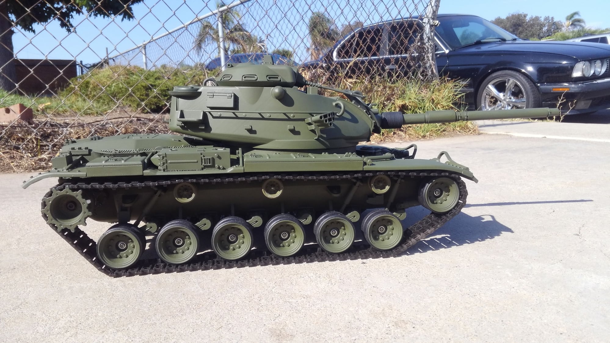
Ok guys, here is a sneak peak. My Grey Desert MERDC Abrams and my buddies Verdant MERDC Abrams. I painted both but he drew the lines on his from a photo other than the one I sent him so the pattern varies a little bit from my tank but that basically the color scheme my m60a3 will look like.
As for the drive shafts. I completed the shaft extensions of 7mm per side. I installed them and then decided they were too long. More eyeballing and laying rulers down etc etc and I decided to hack 1mm off the length of each side off. I re installed the sprockets and tracks and eyeballed and straight edged it over and over and I think they are dead on now.
So the solution was to extend the shaft length by 6mm. That makes the overall shaft from 58mm to 64mm. Just and an FYI for another measurement, my shaft length protruding from the hull is 20mm.
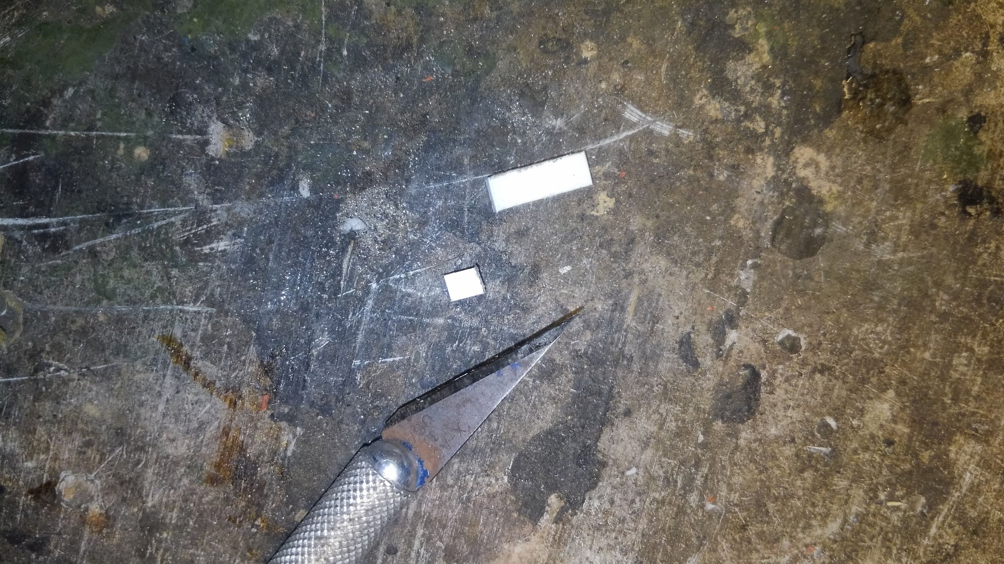
Now here is the kicker. I was cleaning up and I picked up the one plastic HL tan sprocket that I used to help adjust and eyeball measurements and put it back in the HL accessory bag that they included in my kit, (I used metal sprockets) The bag contains the sprockets, HL size sprocket screws, spare plastic track links, and....... two white plastic thingies. I noticed them and pondered their importance. I pulled one out and it was delrin or something similar, and its D shaped, like the axle shaft. I measured it and it is 4.5mm long. It hit me that DKLM included this as a spacer to go inside the sprocket to push it far enough out from the tank to run. The bad thing about doing the spacing this way, one its only 4.5mm and I believe it takes 6mm additional to get a correct alignment, and the other is you take up all the space in the sprocket and are left with very little to hold onto the shaft with. If the track binds or throws your likely to twist that plastic sprocket right off the shaft mounting tube. Any way so there is that mystery solved.
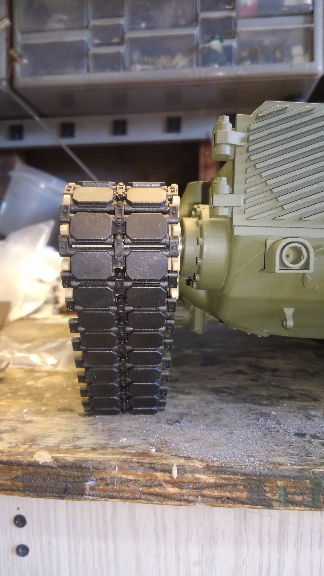
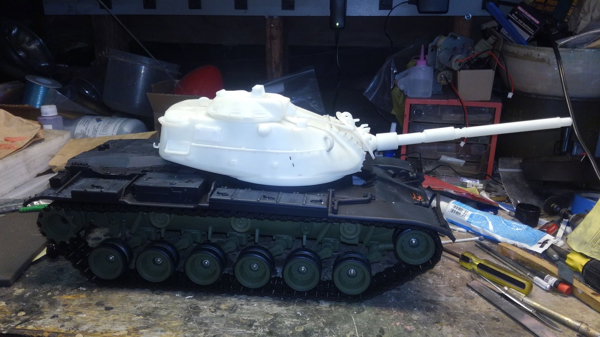
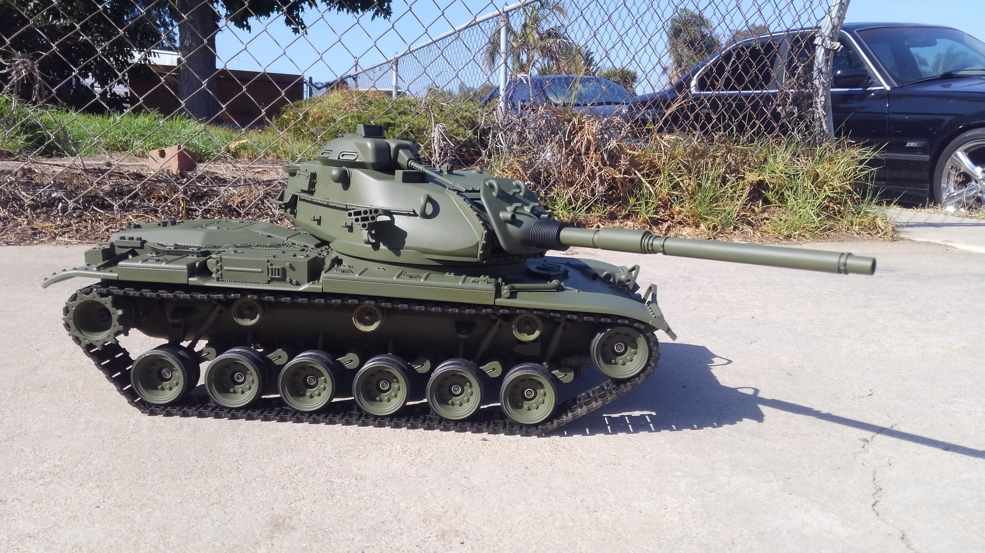
Below you will see the picture of my chassis completed. You can see the drive shafts and that bugs me, real m60s the sprocket is close up to the end of the out drive. So I am thinking about using maybe a HL body bearing like the after market ones for the abrams or T90. that would fill it up a little bit. I'll deal with that later. At least it will run and track correctly now.
On to the upper hull. I have like 8 coats of building primer on the hull and you can still see the faint 3d texture so I decided I had to sand the primer with 400. Ive done the front and the close side in the forground. The lighter areas are sanded. getting around all the handles and bolts and **** is a major pain in the ass worth of time. Im going to sand the upper engine deck too, but it is a bit flexible and the weakest part of the tank. I cracked the rear left corner of it and had to super glue it. That deck is very thin as opposed to the other areas of the tank. So just like how I have braced all my custom Sherman build hulls, I am going to scuff it deep with an exacto all over and then smear bondo into it and then lay in a piece of plexi that I will cut to size to make it super strong. I like beefy tough tanks for when I pick them up so they don't break.
So that's it for now folks. Just a lot more sanding for a while and waiting for hopefully a care package from Carson of all the screws I am missing for all over the turret.


As for the drive shafts. I completed the shaft extensions of 7mm per side. I installed them and then decided they were too long. More eyeballing and laying rulers down etc etc and I decided to hack 1mm off the length of each side off. I re installed the sprockets and tracks and eyeballed and straight edged it over and over and I think they are dead on now.
So the solution was to extend the shaft length by 6mm. That makes the overall shaft from 58mm to 64mm. Just and an FYI for another measurement, my shaft length protruding from the hull is 20mm.
Now here is the kicker. I was cleaning up and I picked up the one plastic HL tan sprocket that I used to help adjust and eyeball measurements and put it back in the HL accessory bag that they included in my kit, (I used metal sprockets) The bag contains the sprockets, HL size sprocket screws, spare plastic track links, and....... two white plastic thingies. I noticed them and pondered their importance. I pulled one out and it was delrin or something similar, and its D shaped, like the axle shaft. I measured it and it is 4.5mm long. It hit me that DKLM included this as a spacer to go inside the sprocket to push it far enough out from the tank to run. The bad thing about doing the spacing this way, one its only 4.5mm and I believe it takes 6mm additional to get a correct alignment, and the other is you take up all the space in the sprocket and are left with very little to hold onto the shaft with. If the track binds or throws your likely to twist that plastic sprocket right off the shaft mounting tube. Any way so there is that mystery solved.
Below you will see the picture of my chassis completed. You can see the drive shafts and that bugs me, real m60s the sprocket is close up to the end of the out drive. So I am thinking about using maybe a HL body bearing like the after market ones for the abrams or T90. that would fill it up a little bit. I'll deal with that later. At least it will run and track correctly now.
On to the upper hull. I have like 8 coats of building primer on the hull and you can still see the faint 3d texture so I decided I had to sand the primer with 400. Ive done the front and the close side in the forground. The lighter areas are sanded. getting around all the handles and bolts and **** is a major pain in the ass worth of time. Im going to sand the upper engine deck too, but it is a bit flexible and the weakest part of the tank. I cracked the rear left corner of it and had to super glue it. That deck is very thin as opposed to the other areas of the tank. So just like how I have braced all my custom Sherman build hulls, I am going to scuff it deep with an exacto all over and then smear bondo into it and then lay in a piece of plexi that I will cut to size to make it super strong. I like beefy tough tanks for when I pick them up so they don't break.
So that's it for now folks. Just a lot more sanding for a while and waiting for hopefully a care package from Carson of all the screws I am missing for all over the turret.
09-18-2018, 06:42 AM
#15
"Now here is the kicker. I was cleaning up and I picked up the one plastic HL tan sprocket that I used to help adjust and eyeball measurements and put it back in the HL accessory bag that they included in my kit, (I used metal sprockets) The bag contains the sprockets, HL size sprocket screws, spare plastic track links, and....... two white plastic thingies. I noticed them and pondered their importance. I pulled one out and it was delrin or something similar, and its D shaped, like the axle shaft. I measured it and it is 4.5mm long. It hit me that DKLM included this as a spacer to go inside the sprocket to push it far enough out from the tank to run. The bad thing about doing the spacing this way, one its only 4.5mm and I believe it takes 6mm additional to get a correct alignment, and the other is you take up all the space in the sprocket and are left with very little to hold onto the shaft with. If the track binds or throws your likely to twist that plastic sprocket right off the shaft mounting tube. Any way so there is that mystery solved."
Sounds to me like our manufacturer planned more on a static model or at most a wood floor runner. Still and all, you are doing a great job on this thing!
Sounds to me like our manufacturer planned more on a static model or at most a wood floor runner. Still and all, you are doing a great job on this thing!
09-20-2018, 06:05 AM
#16
Thread Starter
More progress on the m60. Mostly detail work right now.
The lift rings on the side of the turret were very obtuse in fitting in the holes, in fact they didn't fit IN the holes. The rings kind of sit on the outside of the tapered holes. If I had glued them in they would have just fallen off soon. So I trimmed the tapered cast base back just a bit and drilled each ring out and installed brass rod and then drilled the tank and glued in place.
They are very sturdy now.
I mentioned lots of sanding on the upper deck. There was one spot of printing rash on the rear engine slope that I had to fill with putty and sand, and one obtuse depression up front right behind the nose that needed filling and sanding down. Also the whole front slope seems to be the worst for seeing panelized faceting strips rather than one smooth piece. Im being very carefull to make sure I prime and sand enough to smooth all this out so it wont show when color coated.
Starting to look like a tank now.
09-21-2018, 06:26 AM
#17
Thread Starter
Work progresses. I got most of the bracing I wanted done on the rear deck. A lot more sanding was needed on the turret than I thought. Just primer it when you get it and sand away till your happy.


09-21-2018, 01:27 PM
#18
Wow, the M60 is looking so cool. Have you taken it for a test drive yet?
09-23-2018, 07:44 PM
#21
Thread Starter
Well, I kind of jumped the gun and painted the tank. I realized it forgot to get the basket finished. Not all the details are glued on yet either. I was looking at my photos of real m60a3 tanks at camp Roberts and other places and if you look at my turret there are dots printed on the side of the turret along the hand rail length. They are quite large and noticeable on the model but they are not on the real tanks. Bummer bummer bummer. So I slid the hand rail off and the smoke launchers, and also deciced I cant stand the tow cable brackets since the real ones are little bent Us that I can make with strip brass so I pulled all them out too. I wound up chiseling off the little spots and sanding the side of the turret again. Got a coat of primer on it tonight and will put a few more on tomorrow and then do some 320 sanding then 400.
Next along, I got my IBU2 Ultimate Friday. This is my first new one. I have 8 old IBU2 base units and they have been discontinued. Well, after the learning curve of having the device talk to me and setting up a massive new text file for it I test it out and beat my head on the work bench all day trying to get rid of the lag delay from the throttle thinking its stuck in Inirtia mode. Well, Some tech support later and it turns out the new boards have a built in delay, you move the throttle stick full up and wait, then the tank starts to move. Push the stick full down and the tank does nothing. Slow lower the stick to reverse and it will slowly start reverse after a delay. Well I actually tried to drive the tank like this and had to catch it with my hands because the response is so slow it almost hit the car tires and nearly went off the curb. Needless to say its useless to battle and nearly impossible to drive. So in my opinion the IBU is no longer a viable IR Battle system board. I sent a nice email with my video to the IBU manufacturer and gave him my feed back to get rid of that nasty delay.
If you want to see how the board works here is my video
If you can drive these new blue ultimate boards my hat is off to you as this is really challenging to try to drive or navigate around anything.
Anybody got any old IBU2 boards that work that they no longer use?
Next along, I got my IBU2 Ultimate Friday. This is my first new one. I have 8 old IBU2 base units and they have been discontinued. Well, after the learning curve of having the device talk to me and setting up a massive new text file for it I test it out and beat my head on the work bench all day trying to get rid of the lag delay from the throttle thinking its stuck in Inirtia mode. Well, Some tech support later and it turns out the new boards have a built in delay, you move the throttle stick full up and wait, then the tank starts to move. Push the stick full down and the tank does nothing. Slow lower the stick to reverse and it will slowly start reverse after a delay. Well I actually tried to drive the tank like this and had to catch it with my hands because the response is so slow it almost hit the car tires and nearly went off the curb. Needless to say its useless to battle and nearly impossible to drive. So in my opinion the IBU is no longer a viable IR Battle system board. I sent a nice email with my video to the IBU manufacturer and gave him my feed back to get rid of that nasty delay.
If you want to see how the board works here is my video
Anybody got any old IBU2 boards that work that they no longer use?
09-24-2018, 08:10 AM
#22
Nice looking build!!!!
 09-25-2018, 03:25 PM
#25
Thread Starter
Im surprised you caught that good for you.
The rear torsion arm torsion bars are stiffer than the rest of the tank. The original supplied mato gear boxes are heavier than thaigen ones, and i suspect the cross drive dklm uses is even heavier. I am going to drop a brick of lead in there, really a bag of shot and see if that helps. The tank is getting heavy and i dont even have metal tracks yet.
wait till you guys see the tank operate and come to life eventually, and the cammo job coming too.