


CARF Galloping Ghost build
 08-05-2020, 05:42 AM
#151

Thread Starter

I hope all is well with you. I don't check in flight and I really want to do that. I have Jeti radio and was wondering if there's a way with take the Kolm RPM data and use Jeti telemetry to transmit without getting the Jeti RMP sensor. I do plan to add this at end of season.

The following users liked this post:
wing13z (08-05-2020)
08-11-2020, 12:22 AM
#152

HI Tom,
I hope all is well with you. I don't check in flight and I really want to do that. I have Jeti radio and was wondering if there's a way with take the Kolm RPM data and use Jeti telemetry to transmit without getting the Jeti RMP sensor. I do plan to add this at end of season.
I hope all is well with you. I don't check in flight and I really want to do that. I have Jeti radio and was wondering if there's a way with take the Kolm RPM data and use Jeti telemetry to transmit without getting the Jeti RMP sensor. I do plan to add this at end of season.
it is ! go for the sparkwitch pro!
09-15-2020, 10:26 PM
#156
09-16-2020, 05:52 AM
#157
Thread Starter
Hi orthobird,
I'm curious as well to what engine. congrats on getting the new plane. You'll really like it and it's definitely a plane you don't see at the field. Every time I fly it, people seem to what to stop and watch. I have all the photos from CARF on either the DA100 or the Kolm 230 build if you'd like.
Rob
 10-10-2020, 03:34 PM
#160
Hey guys, have CARF fixed the gear rail alignment issue on this version of the mustang to line then up with the strut doors better or do you still have to redo the gear rails to get this right?
10-10-2020, 08:56 PM
#162
i think no. This is why they build it only with one hinge for each door. As you do it like in the video above , It works.
10-17-2020, 04:13 AM
#164

My Feedback: (1)
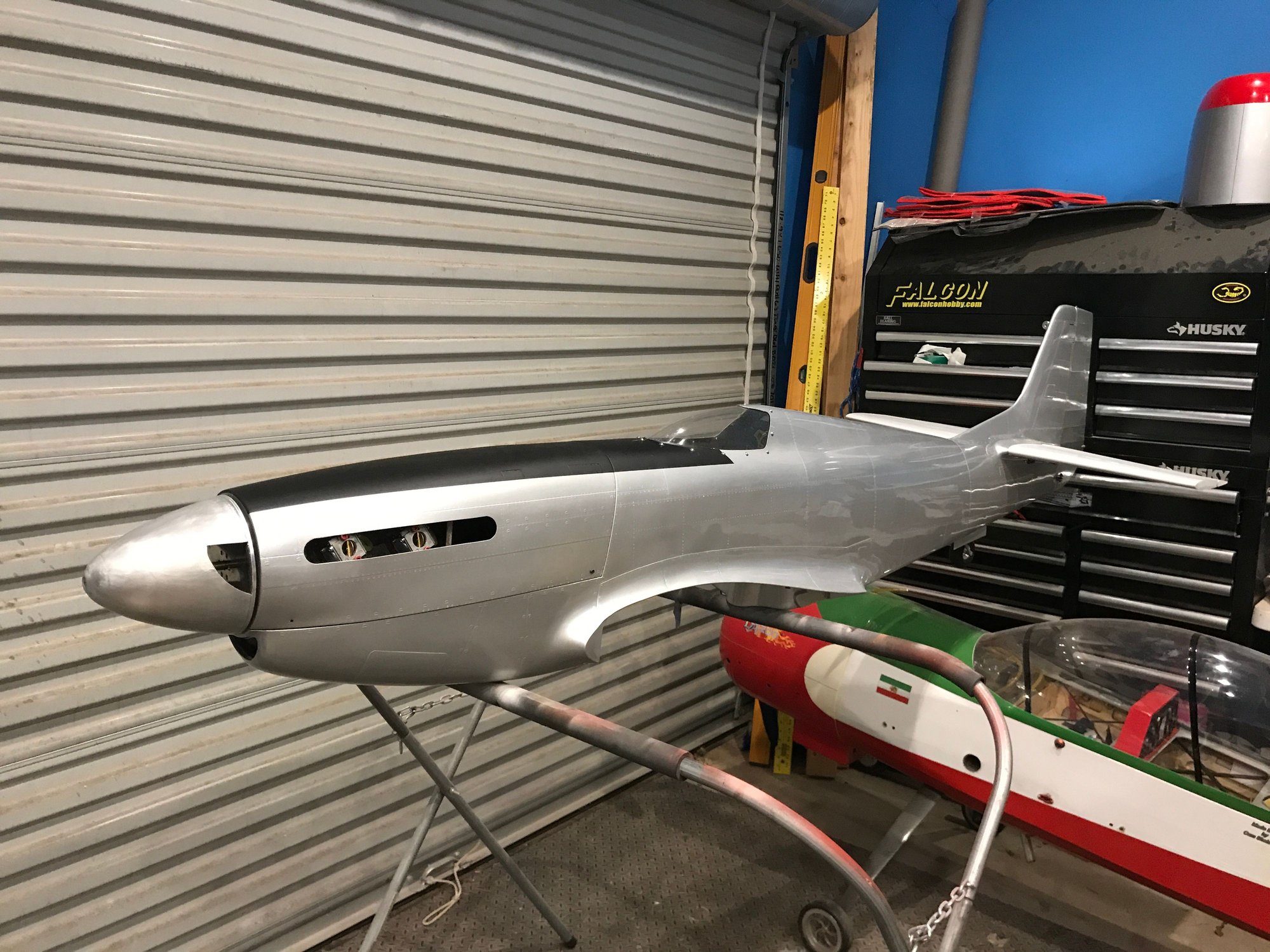
wanted to share these pictures of installing the baffling kit for a DA 100 inline in the CARF GG P-51.
I did not show the pictures of installing the firewall doubler and the long threaded screws, but once that is installed, and the measurements have to be just perfect for this to work out. SO that 1st step is critical.
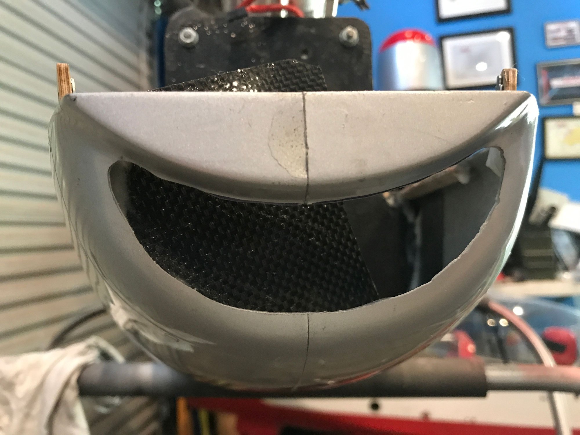
After that, then the next step is to cut out the hole in the front of the bottom of the cowl for the air entry:

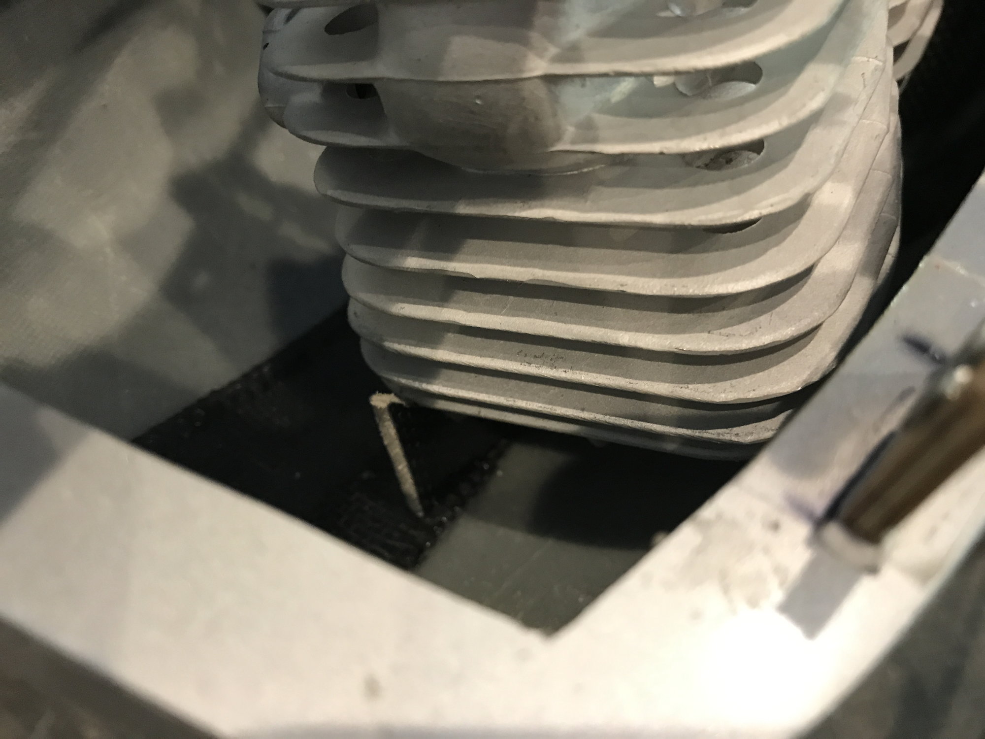
then, you will notice that on the firewall doubler, there are two slot. these two slots are for the cylinder head baffle plate tabs. the baffle plate has two tabs. these will key into the firewall. Does not get easier than that. But, the placement is critical in that, the front end of the plate has to be positioned such that, the spark plug cap clears it. I will demonstrate in next few pictures. But once you have it positioned where you want it, then drop some thin CA to provisionally hold it in place.
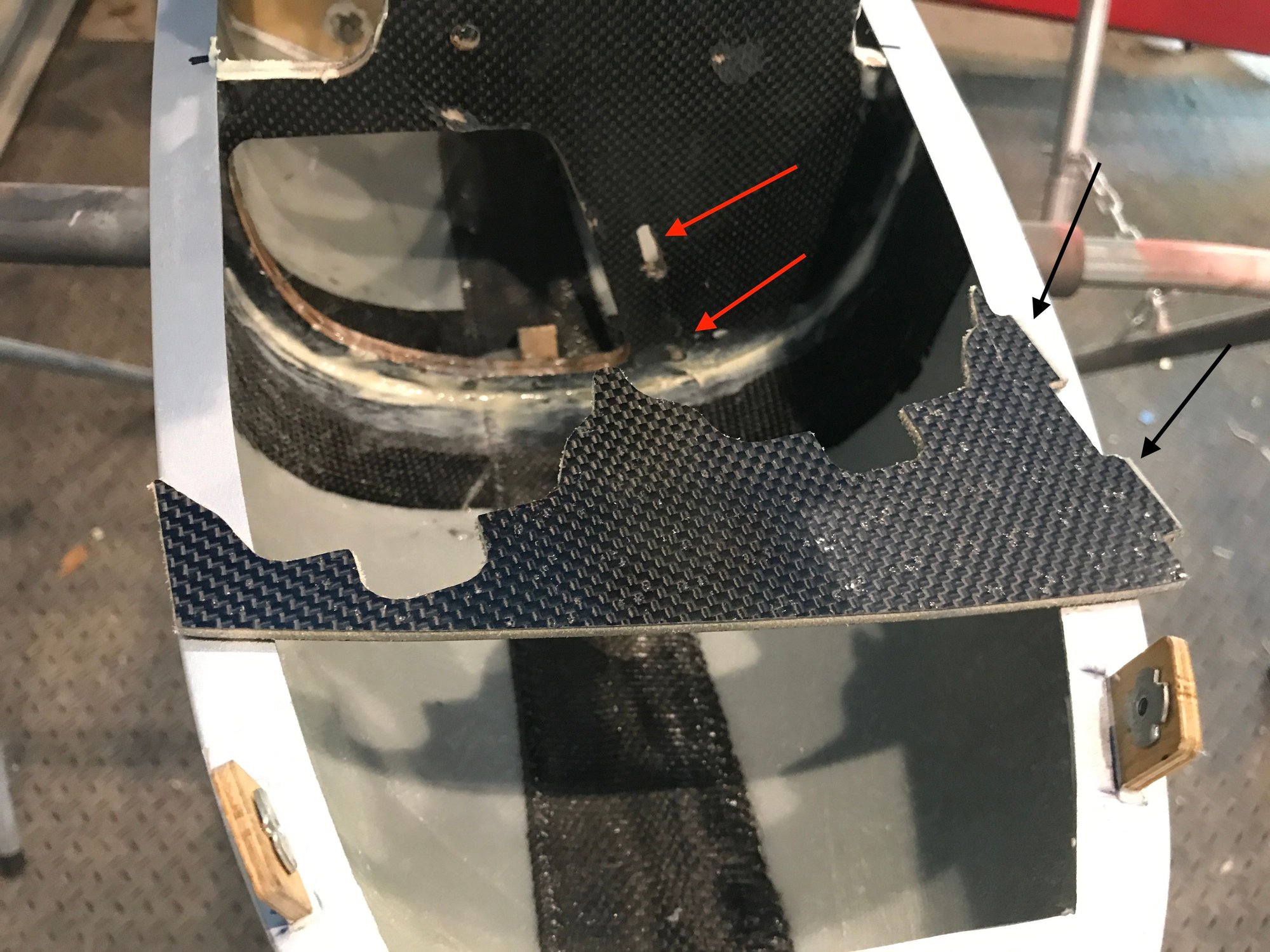
as I was test fitting it, it was binding, so I got my dremel, and cleared any glue that was in the way until it was fully engaged.

this is demonstrating the intimate contact between the back end of the baffle plate and the firewall. This cannot be off by even 1 mm, as this will throw everything else off. SO check this 1st before committing to gluing it.

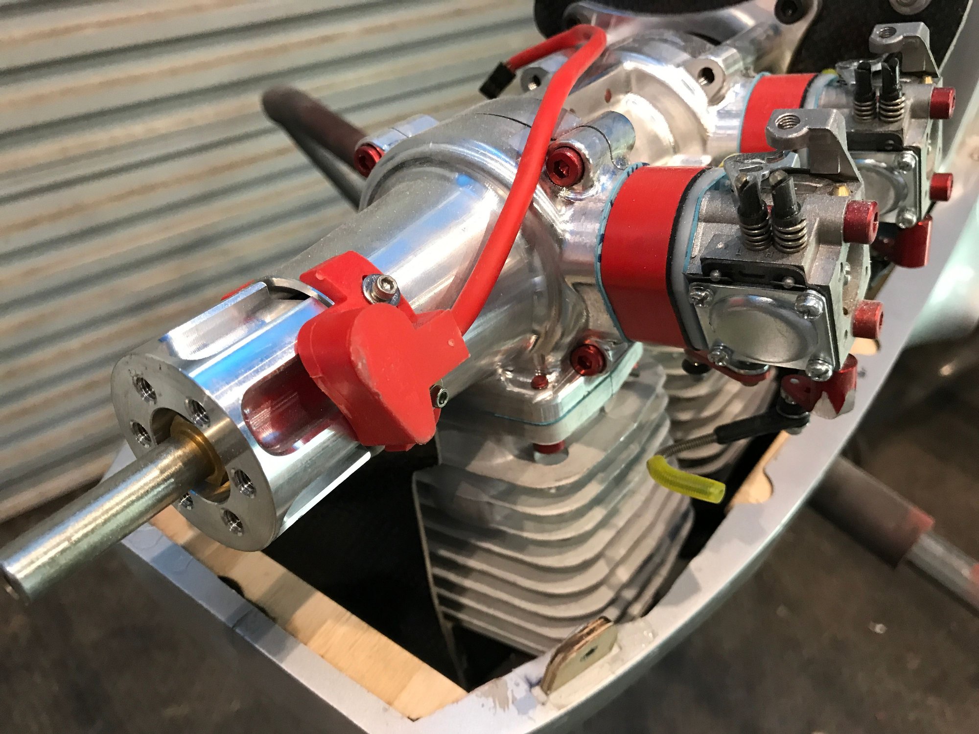
another view of test fitting it. No glue yet. I will then install the motor and see how it fits and if the spark plug caps will clear it.
in this position, the spark plug cap will not fit, so it has to be slid slightly more to the left. Not only that, you can place it so that it lines up with the front air diverter plate. I will demonstrate.
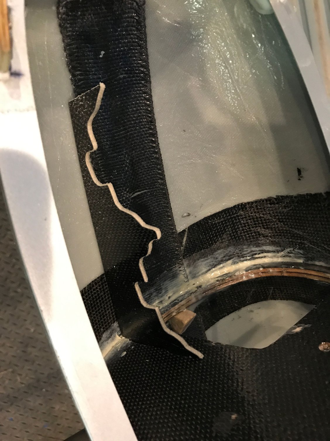
this is the top plenum. You will need to test fit it and then mark with a sharpie the outline on the left side and the front side, and then with a dremel, cut out part of the front end of the fuselage so that it keys in perfectly.
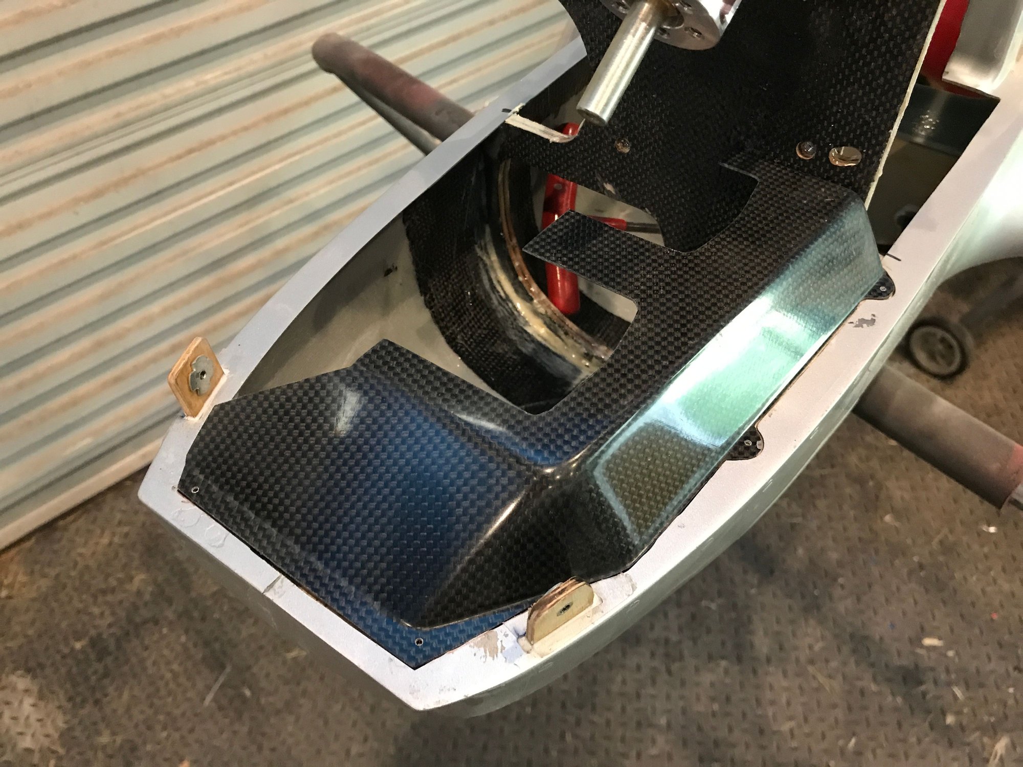
this picture demonstrates the air diverter plate. the left side of this should line up with the front end of the cylinder head baffle plate. As pictured. Apply a drop of thin CA to help hold it place, and then reinstall the motor to make sure everything is well aligned.

SO here it is, so far, so good. It is all fitting well.
another view of the front diverter plate.
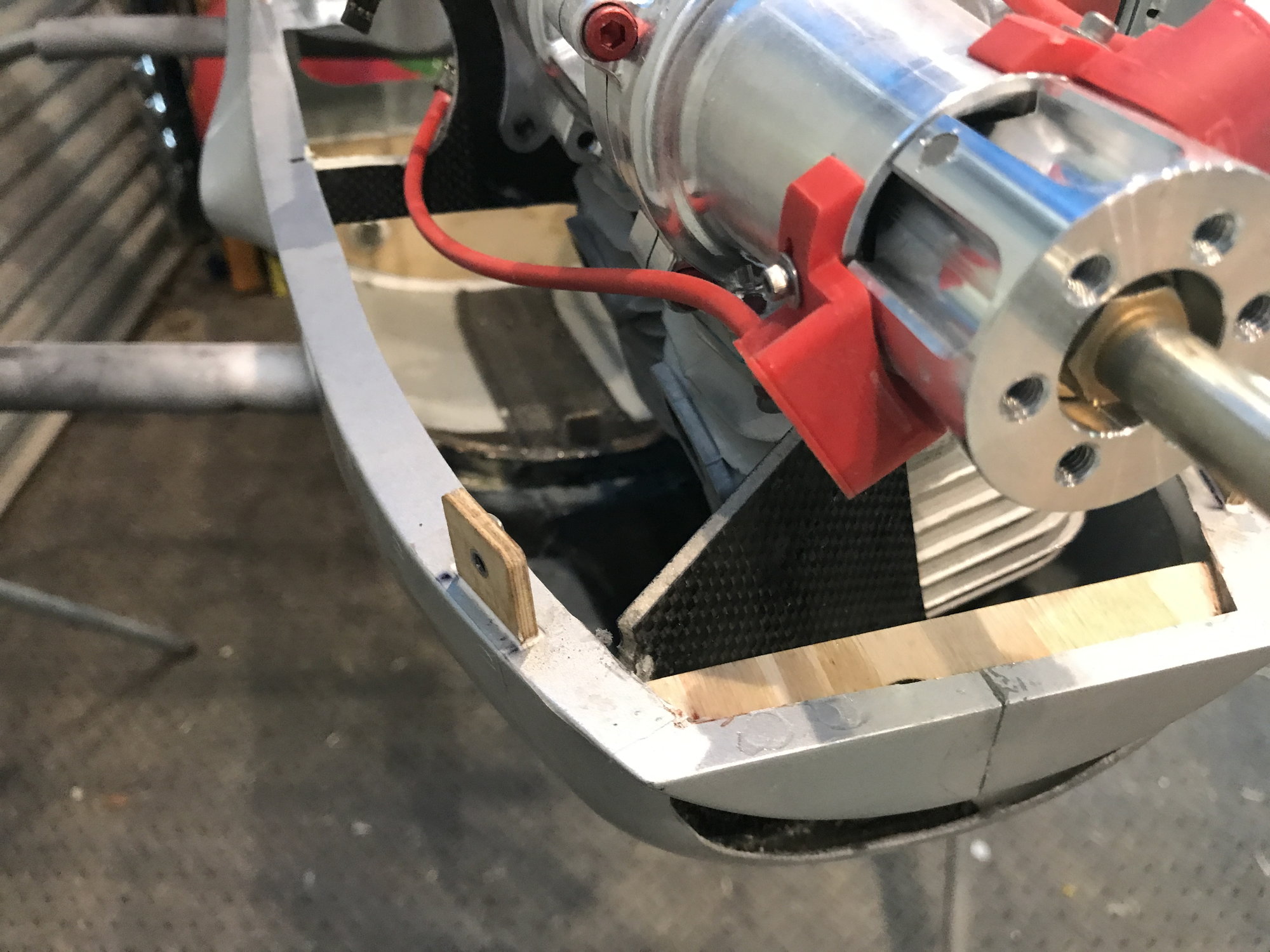
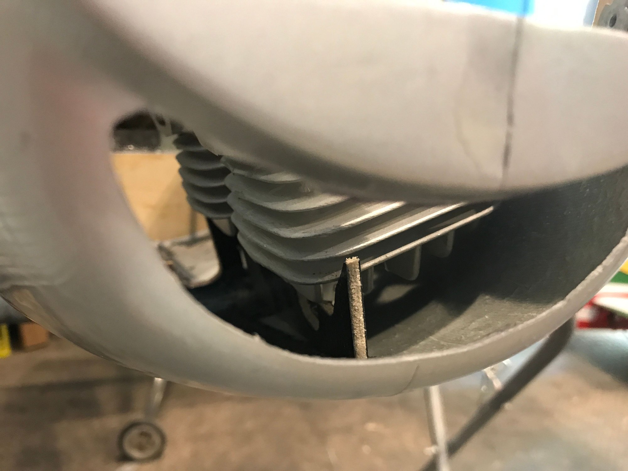
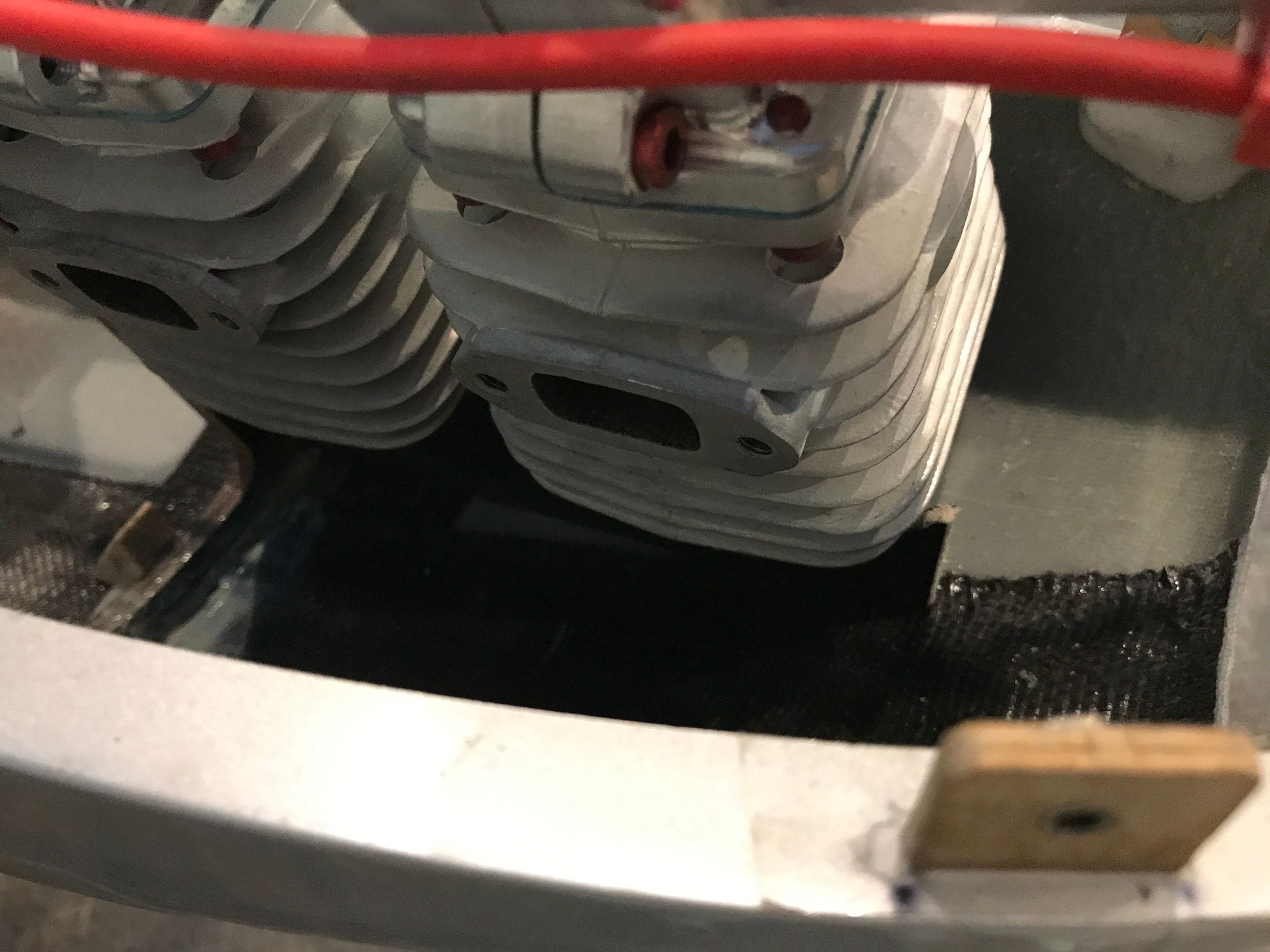
Looking from the front air inlet, the air diverter will direct the air flow towards the left side of the cowl, and now the air will rush thru the cylinder fins and then down to the right side of the motor.
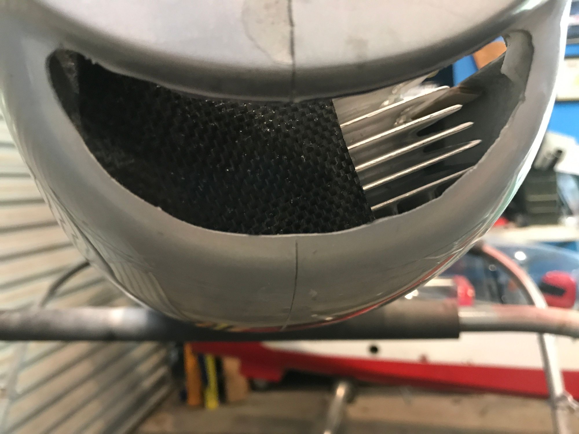
this is the side where the air will travel once air is forced thru the cylinder fins. I did force compressed air thru the front air scoop, and it was all passing out in this area. Really cool!
after liking it all, I installed the plenum and drilled for the 4 screws, then I removed it and filled the holes with CA. Next step is to apply the 30 minute epoxy mixed with milled fiberglass and micro-balloons.
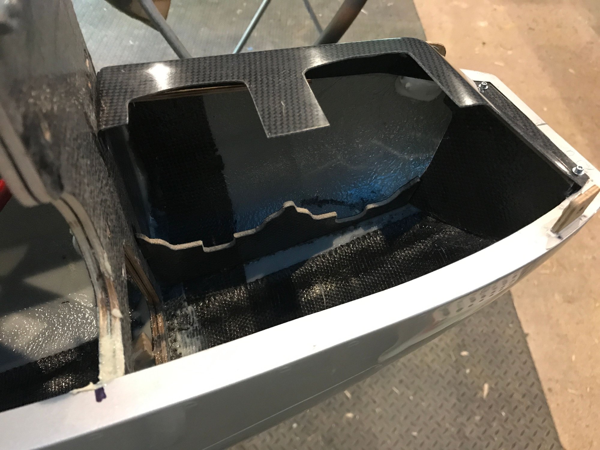


these next pictures show where I placed the fillet of epoxy and micro-balloons with milled FG.


KS sells a spinner that is 6.25" in diameter. I had to cut out the holes for the propeller blades, it costs about 80 euros. I did send an EMAIL to CARF and they state that the airplane will not require down thrust, but, it is best to line up the prop spinner back plate to the fuselage and make it align well, and then deal with a rudder to throttle mix to counter the torque. I am ok with that.
I followed the instructions from Tru Turn on how to polish a spinner. 320 wet, followed by 400 wet, then 600 wet. Makes a huge mess, and then I buffed it, all by hand, using 3M polish and rubbing compound. There are still some machining marks on the spinner, and if my hands were not cramping, I would have kept working on it. I think I may have carpal tunnel syndrome.

i think I got it aligned pretty well.

I did not show the pictures of installing the firewall doubler and the long threaded screws, but once that is installed, and the measurements have to be just perfect for this to work out. SO that 1st step is critical.
After that, then the next step is to cut out the hole in the front of the bottom of the cowl for the air entry:
then, you will notice that on the firewall doubler, there are two slot. these two slots are for the cylinder head baffle plate tabs. the baffle plate has two tabs. these will key into the firewall. Does not get easier than that. But, the placement is critical in that, the front end of the plate has to be positioned such that, the spark plug cap clears it. I will demonstrate in next few pictures. But once you have it positioned where you want it, then drop some thin CA to provisionally hold it in place.
as I was test fitting it, it was binding, so I got my dremel, and cleared any glue that was in the way until it was fully engaged.
this is demonstrating the intimate contact between the back end of the baffle plate and the firewall. This cannot be off by even 1 mm, as this will throw everything else off. SO check this 1st before committing to gluing it.
another view of test fitting it. No glue yet. I will then install the motor and see how it fits and if the spark plug caps will clear it.
in this position, the spark plug cap will not fit, so it has to be slid slightly more to the left. Not only that, you can place it so that it lines up with the front air diverter plate. I will demonstrate.
this is the top plenum. You will need to test fit it and then mark with a sharpie the outline on the left side and the front side, and then with a dremel, cut out part of the front end of the fuselage so that it keys in perfectly.
this picture demonstrates the air diverter plate. the left side of this should line up with the front end of the cylinder head baffle plate. As pictured. Apply a drop of thin CA to help hold it place, and then reinstall the motor to make sure everything is well aligned.
SO here it is, so far, so good. It is all fitting well.
another view of the front diverter plate.
Looking from the front air inlet, the air diverter will direct the air flow towards the left side of the cowl, and now the air will rush thru the cylinder fins and then down to the right side of the motor.
this is the side where the air will travel once air is forced thru the cylinder fins. I did force compressed air thru the front air scoop, and it was all passing out in this area. Really cool!
after liking it all, I installed the plenum and drilled for the 4 screws, then I removed it and filled the holes with CA. Next step is to apply the 30 minute epoxy mixed with milled fiberglass and micro-balloons.
these next pictures show where I placed the fillet of epoxy and micro-balloons with milled FG.
KS sells a spinner that is 6.25" in diameter. I had to cut out the holes for the propeller blades, it costs about 80 euros. I did send an EMAIL to CARF and they state that the airplane will not require down thrust, but, it is best to line up the prop spinner back plate to the fuselage and make it align well, and then deal with a rudder to throttle mix to counter the torque. I am ok with that.
I followed the instructions from Tru Turn on how to polish a spinner. 320 wet, followed by 400 wet, then 600 wet. Makes a huge mess, and then I buffed it, all by hand, using 3M polish and rubbing compound. There are still some machining marks on the spinner, and if my hands were not cramping, I would have kept working on it. I think I may have carpal tunnel syndrome.
i think I got it aligned pretty well.
The following users liked this post:
ChrisPetersen (02-27-2022)
 10-22-2020, 03:05 AM
#168
My Feedback: (1)
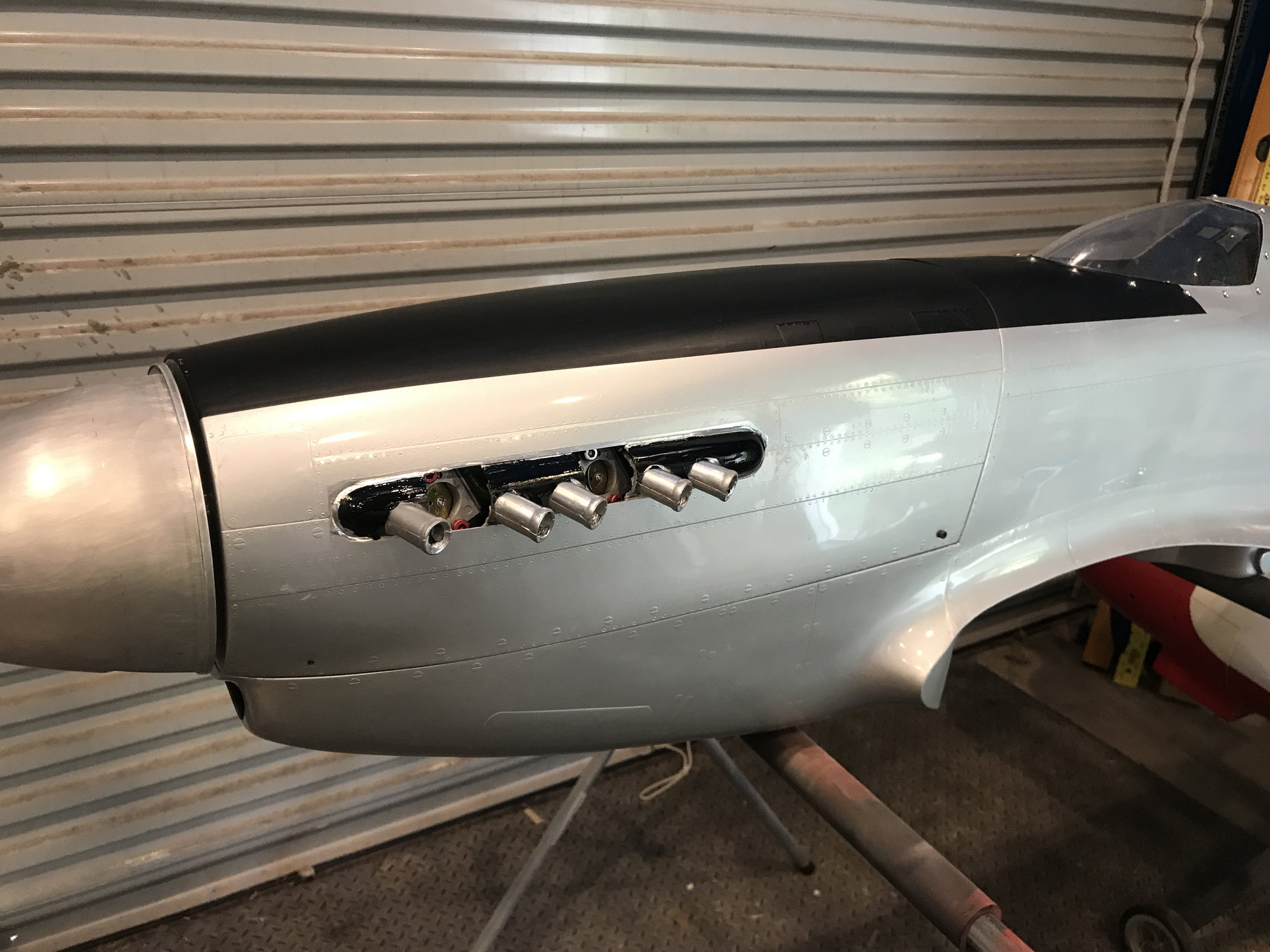
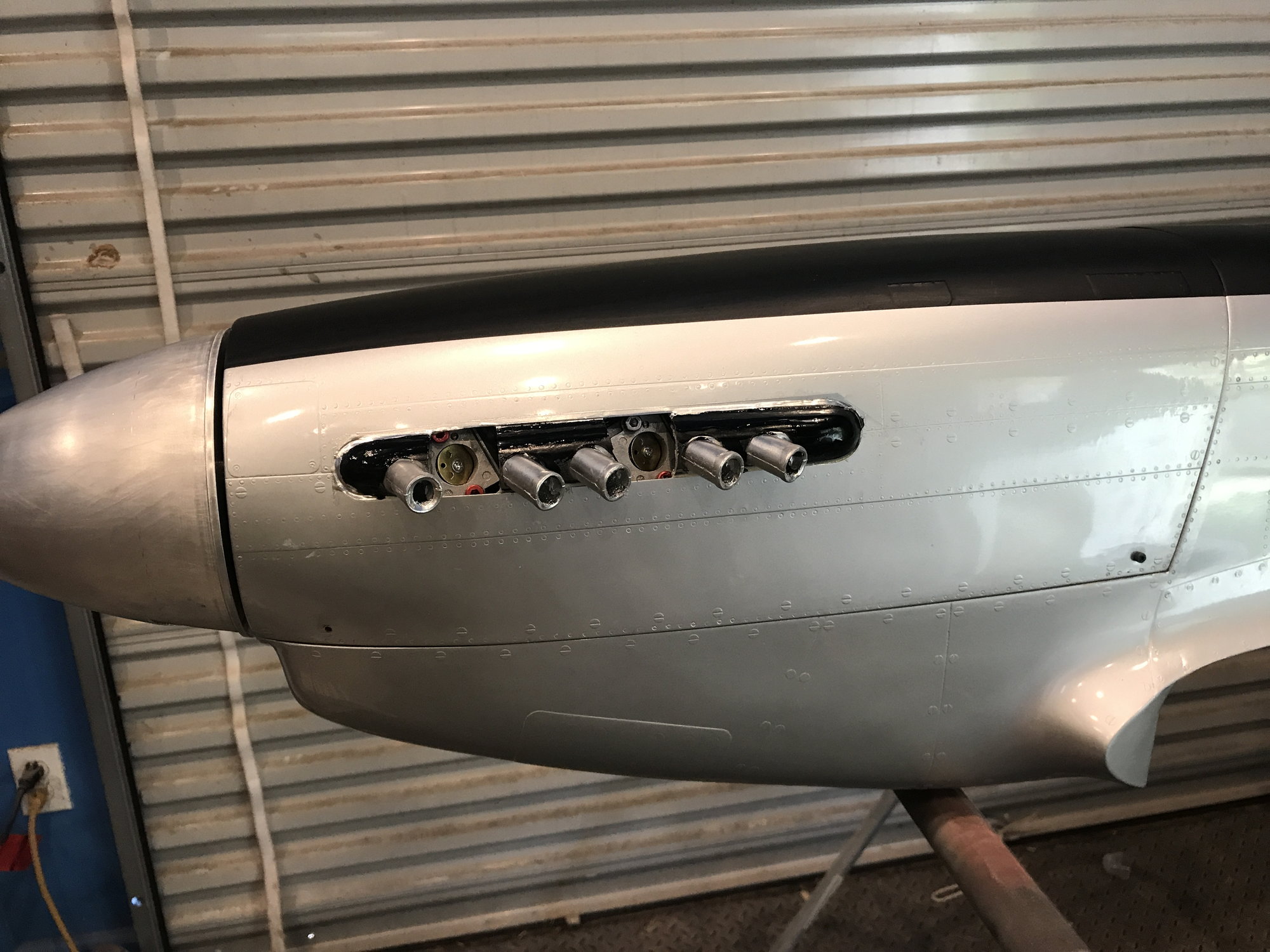
i was able to manufacture a custom exhaust that is functional.
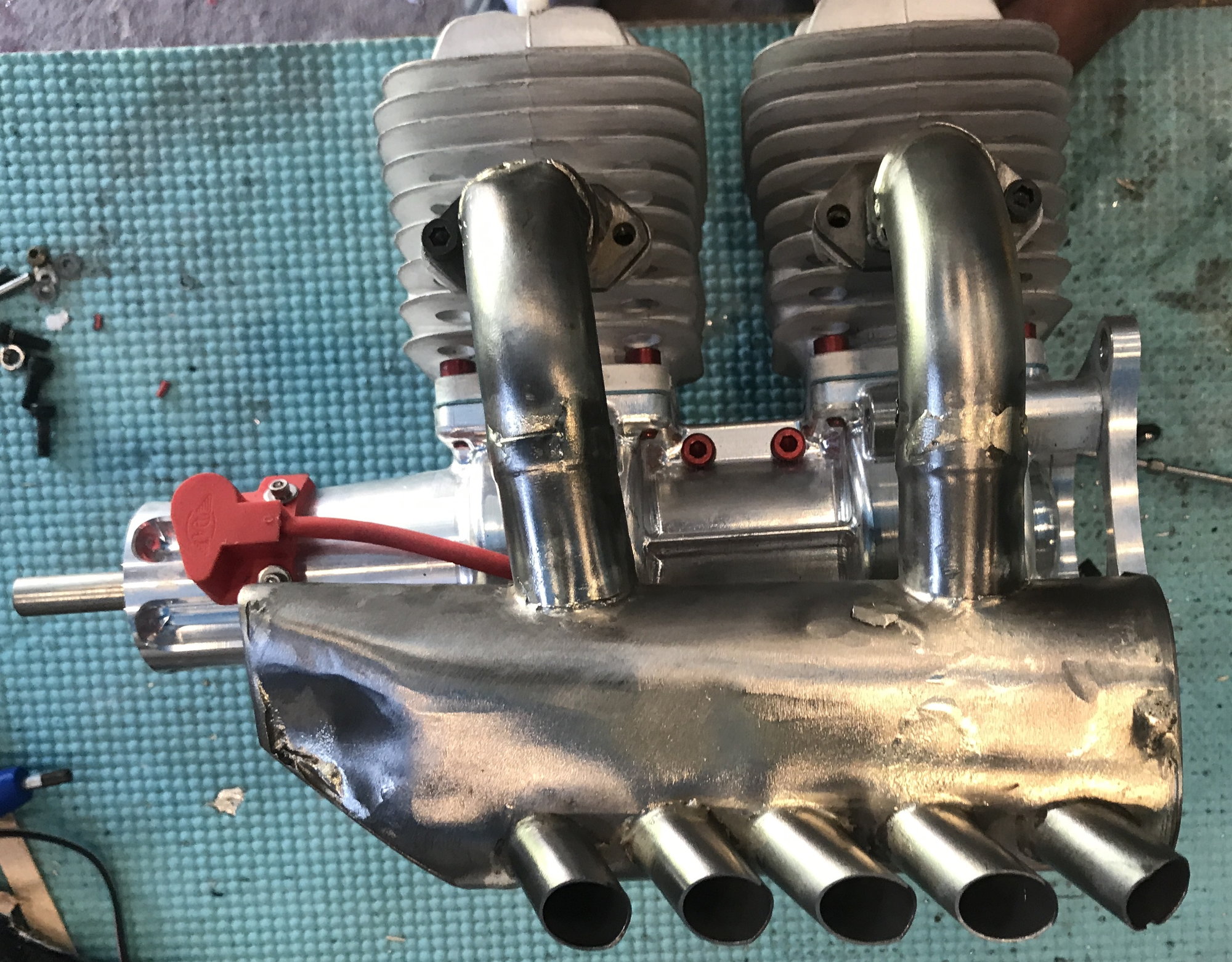
Inline DA 100
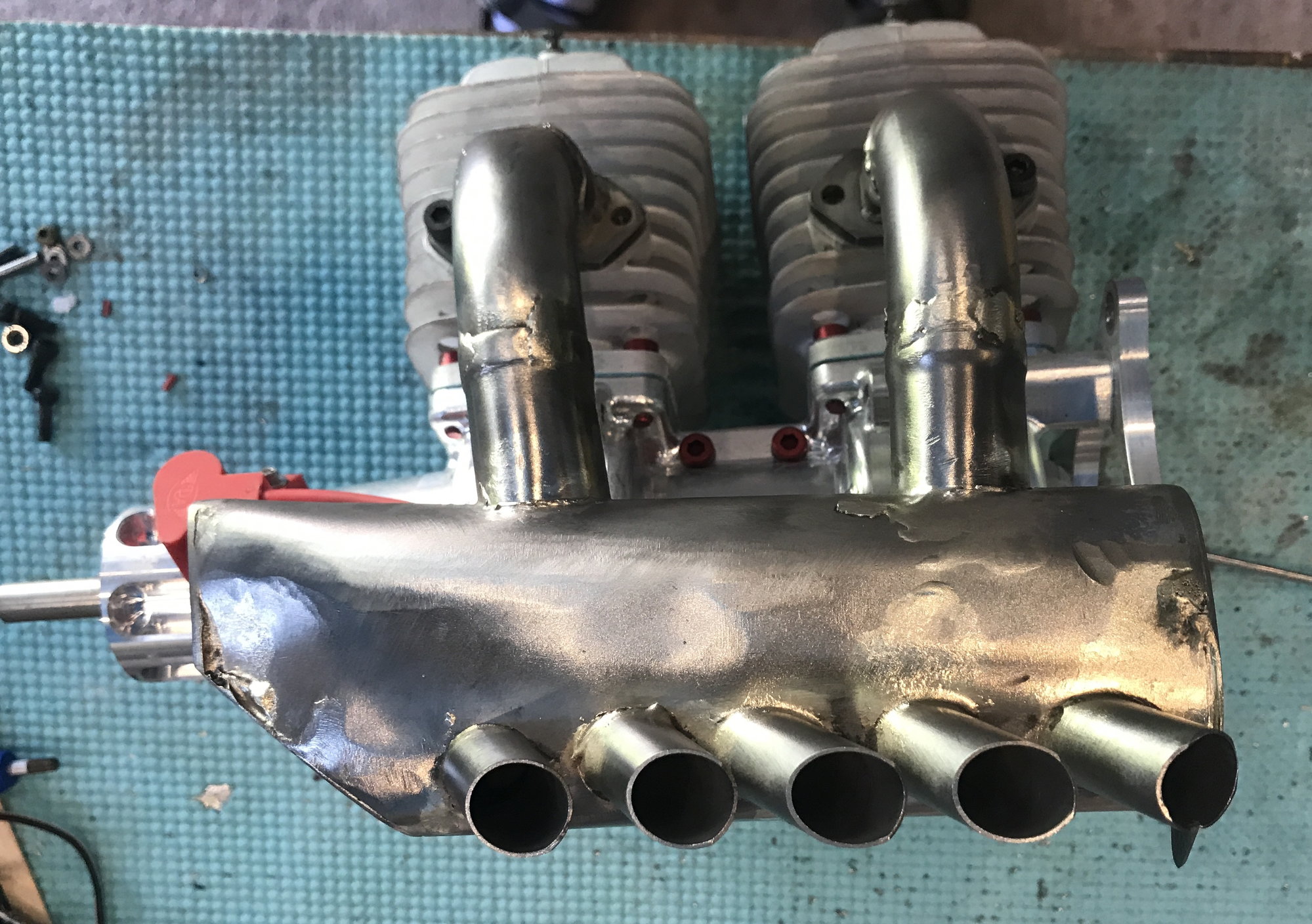
Stainless steel tubing from McMaster Carr

KS exhaust flanges and KS 90 degree bends. tubing from flange to muffler is 25 mm diameter.

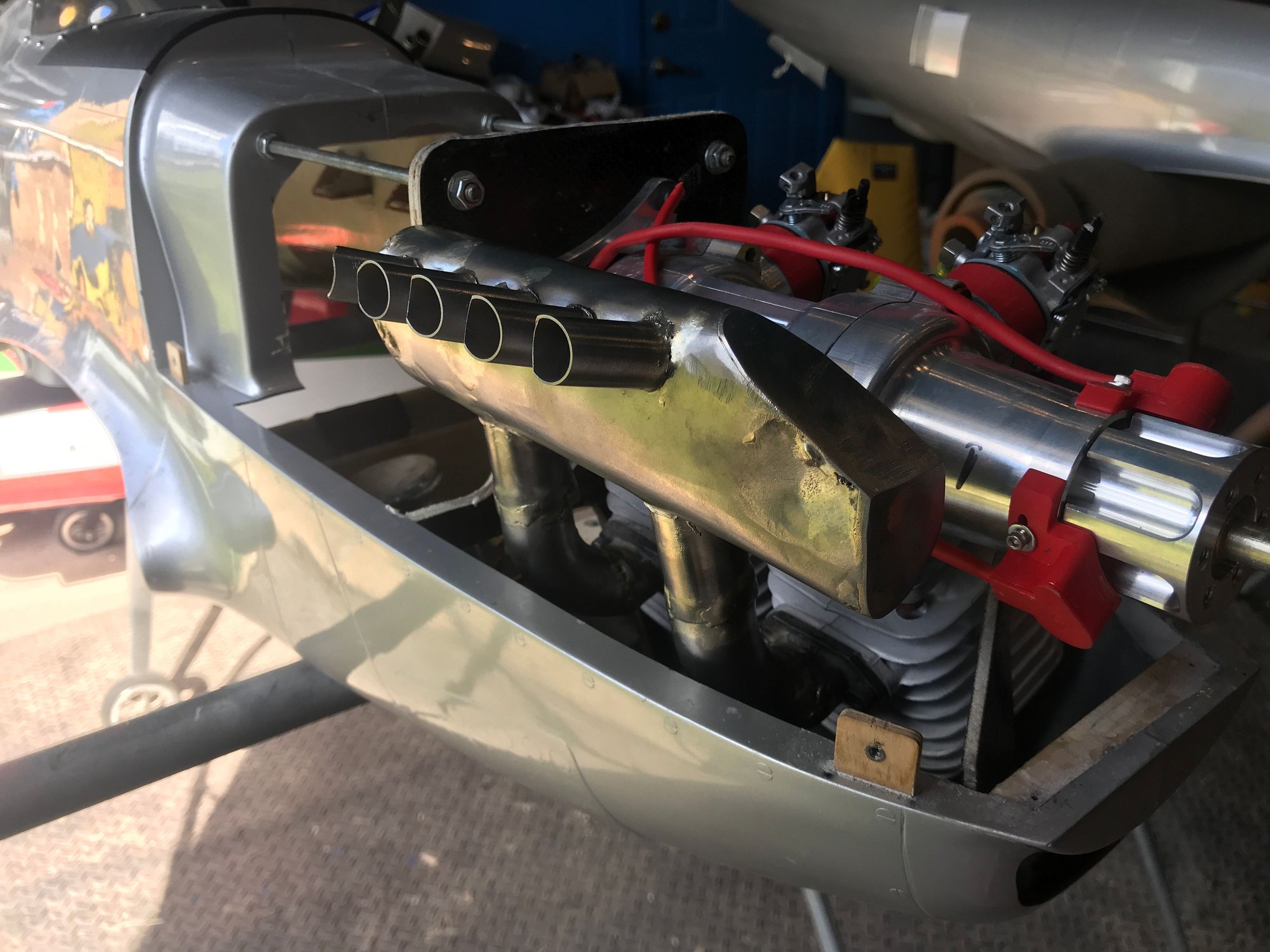
front end of muffler had to be relieved in order for it to not touch the cowl.


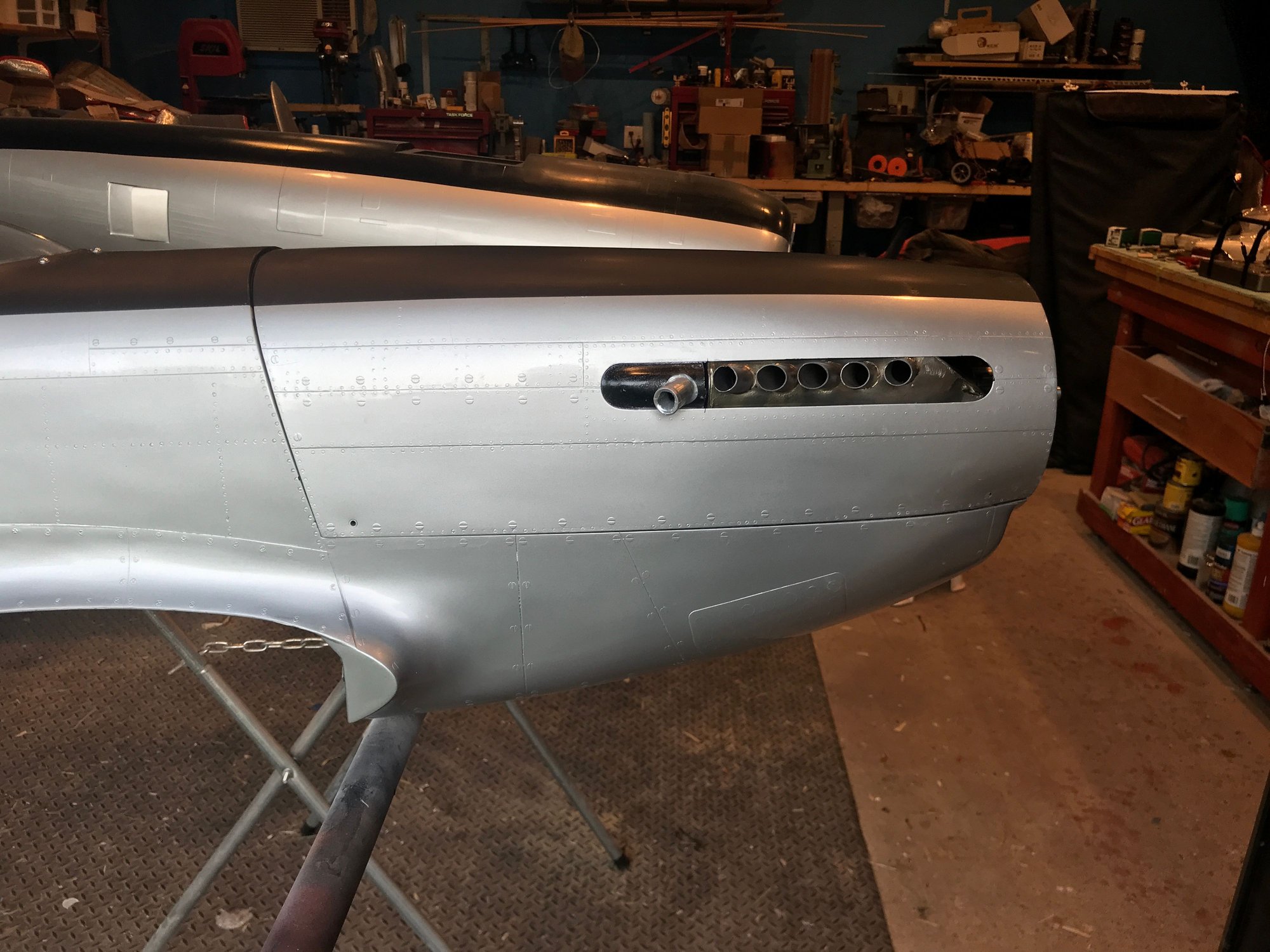
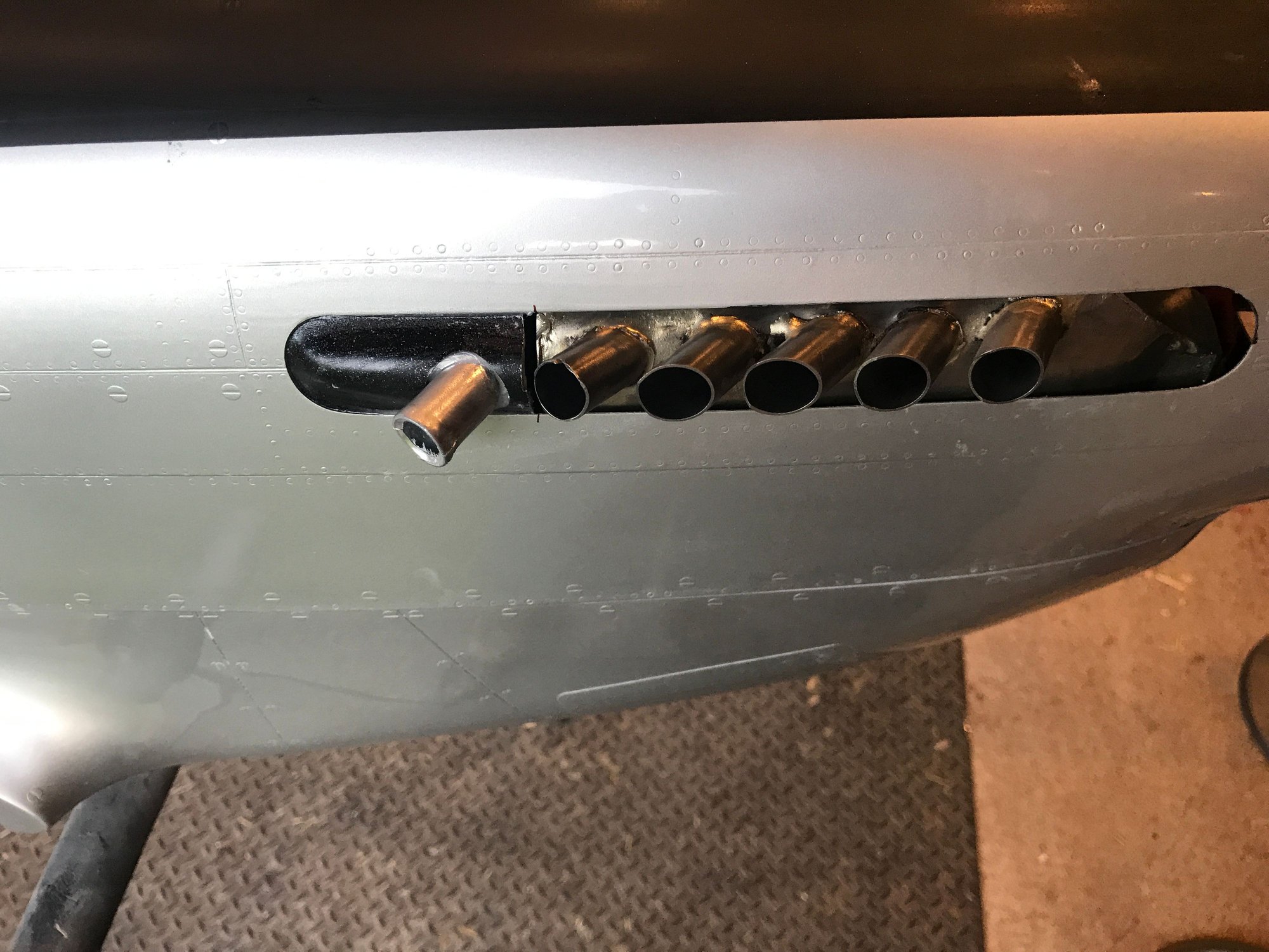
this plastic mock exhaust stack, the furthest back, is open, so somewhat functional, in that it will allow hot air to exit. all of the stacks on left side are also open, to allow hot air to exit
Inline DA 100
Stainless steel tubing from McMaster Carr
KS exhaust flanges and KS 90 degree bends. tubing from flange to muffler is 25 mm diameter.
front end of muffler had to be relieved in order for it to not touch the cowl.
this plastic mock exhaust stack, the furthest back, is open, so somewhat functional, in that it will allow hot air to exit. all of the stacks on left side are also open, to allow hot air to exit
10-22-2020, 03:14 AM
#169
My Feedback: (1)
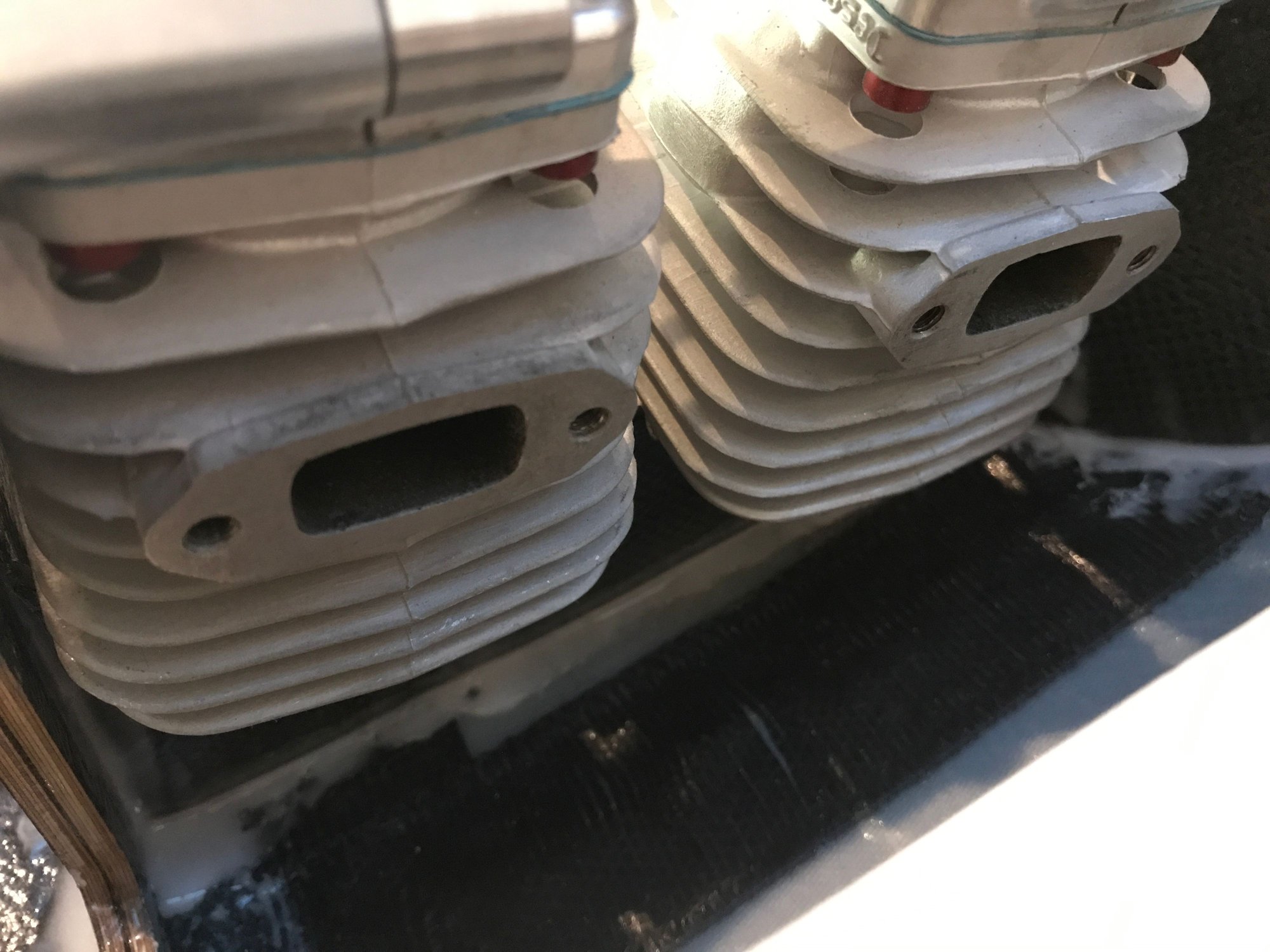
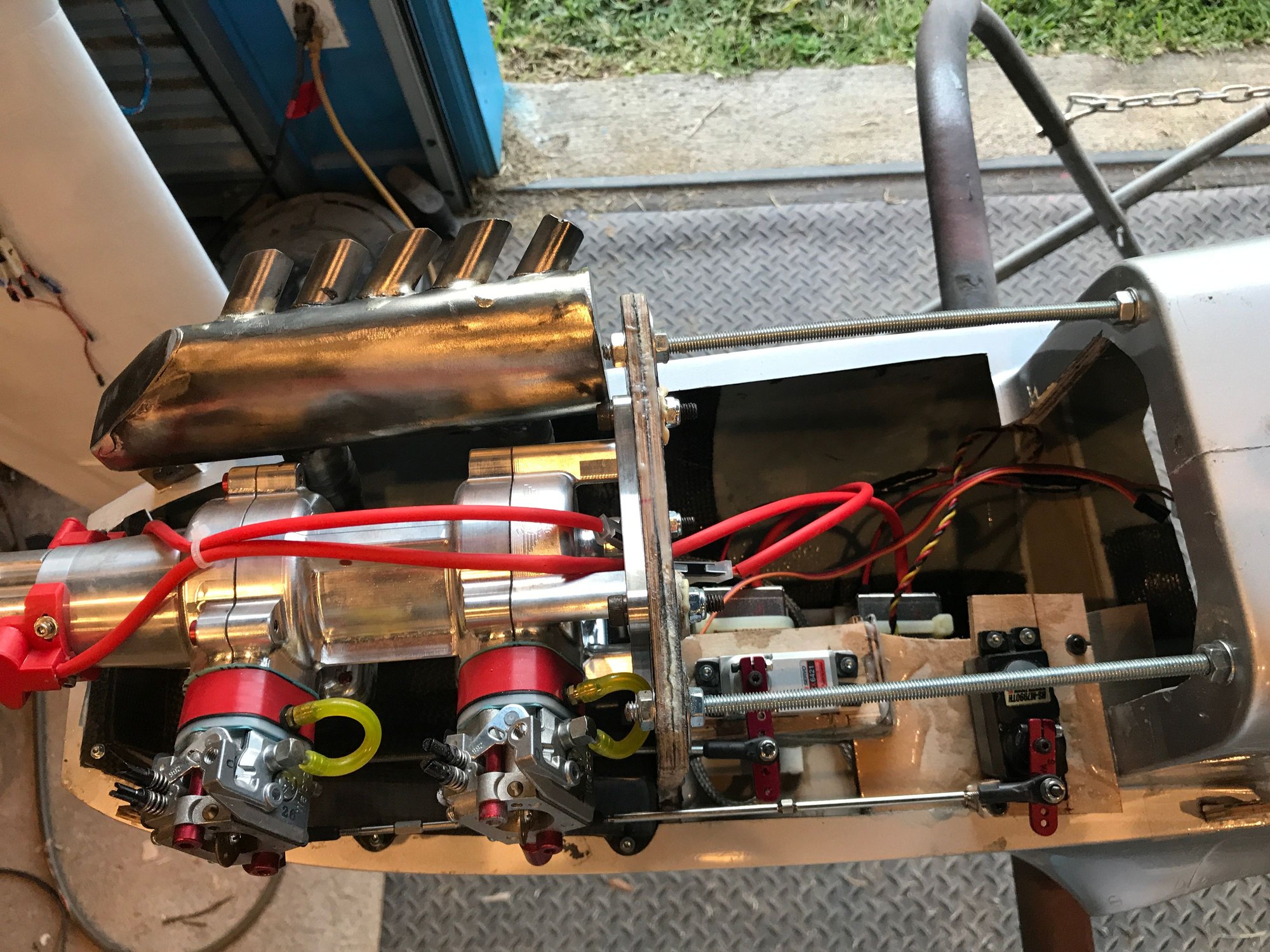
Wanted to share the baffling for the DA 100 inline and also how I installed the throttle servo, the choke servo, and the ignition units.
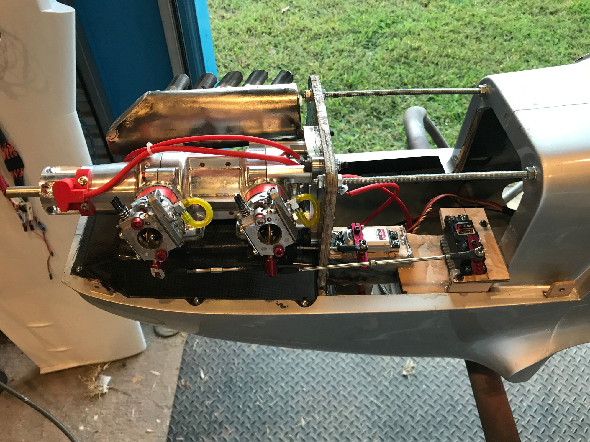
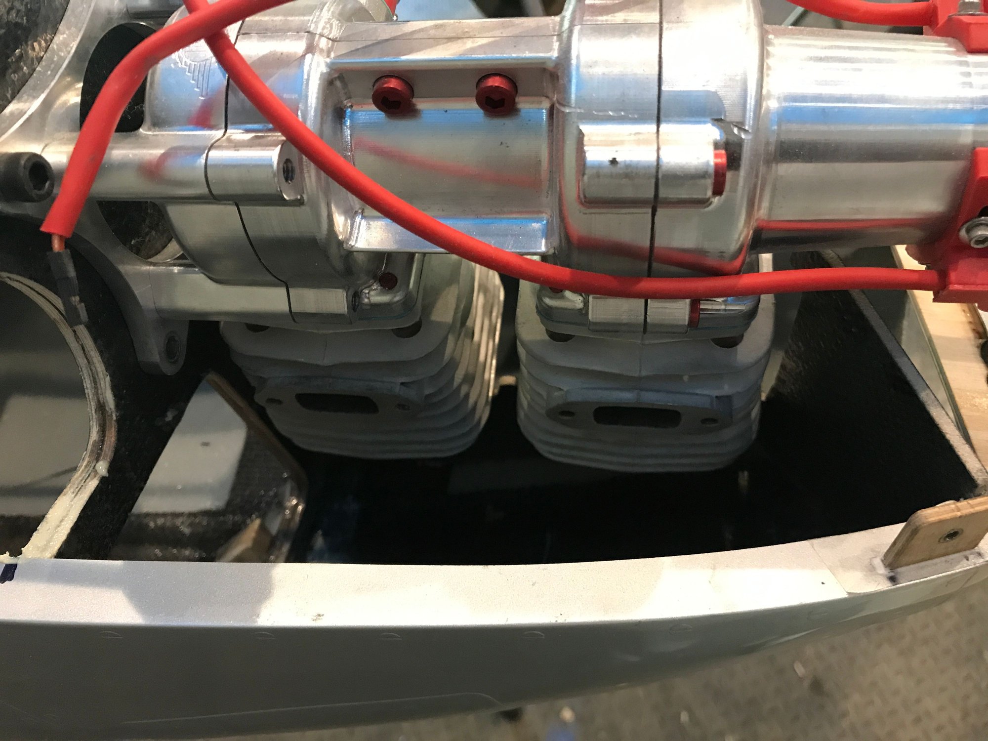
DA 100 inline, baffling shroud is also installed.
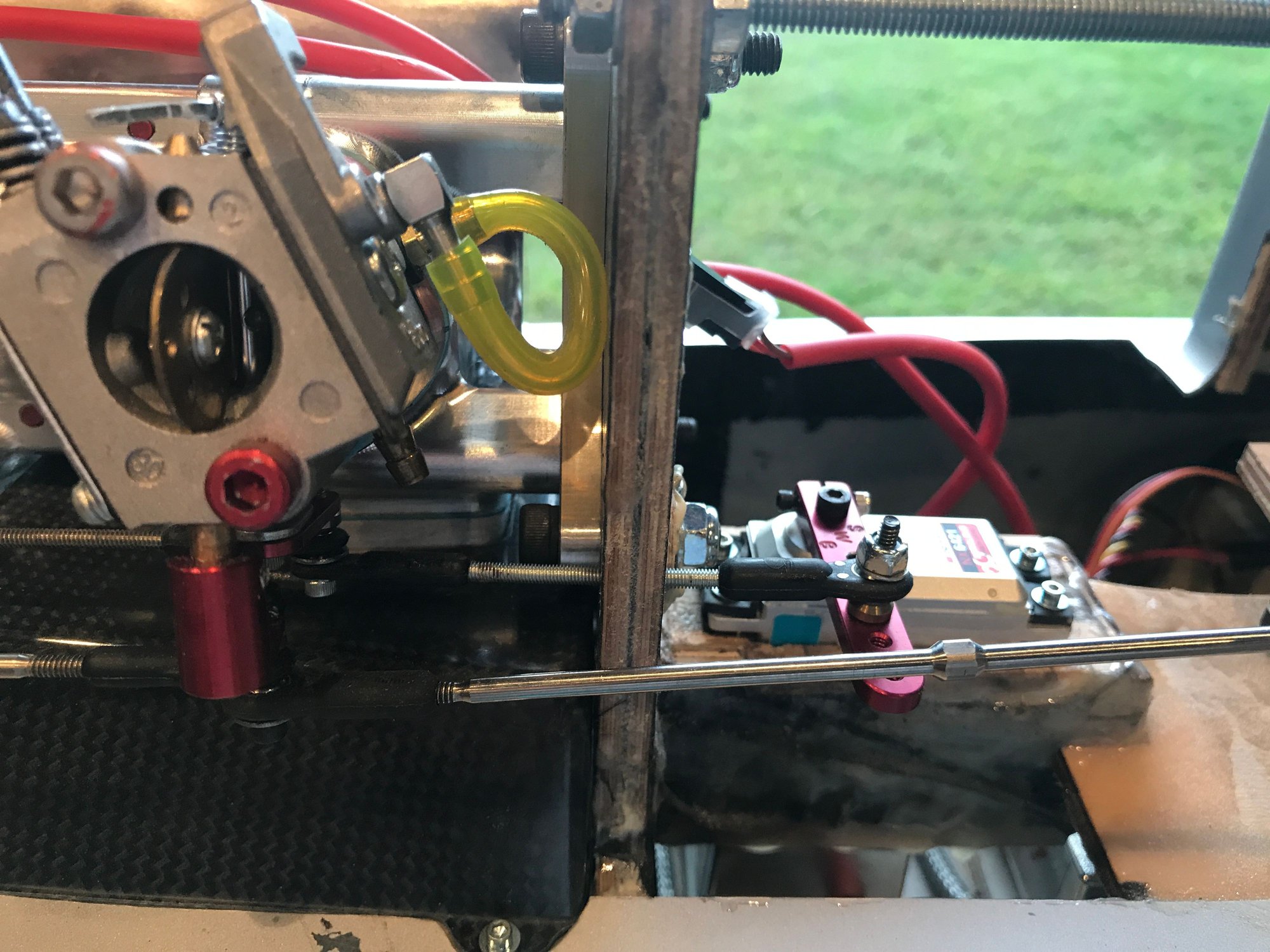
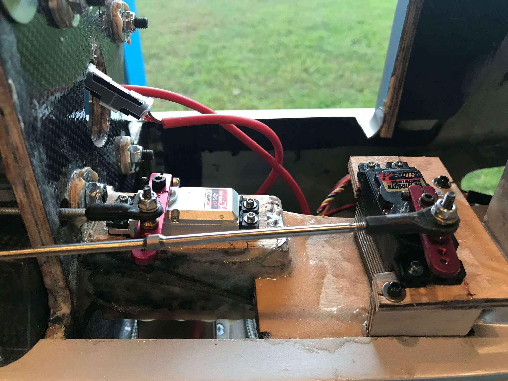
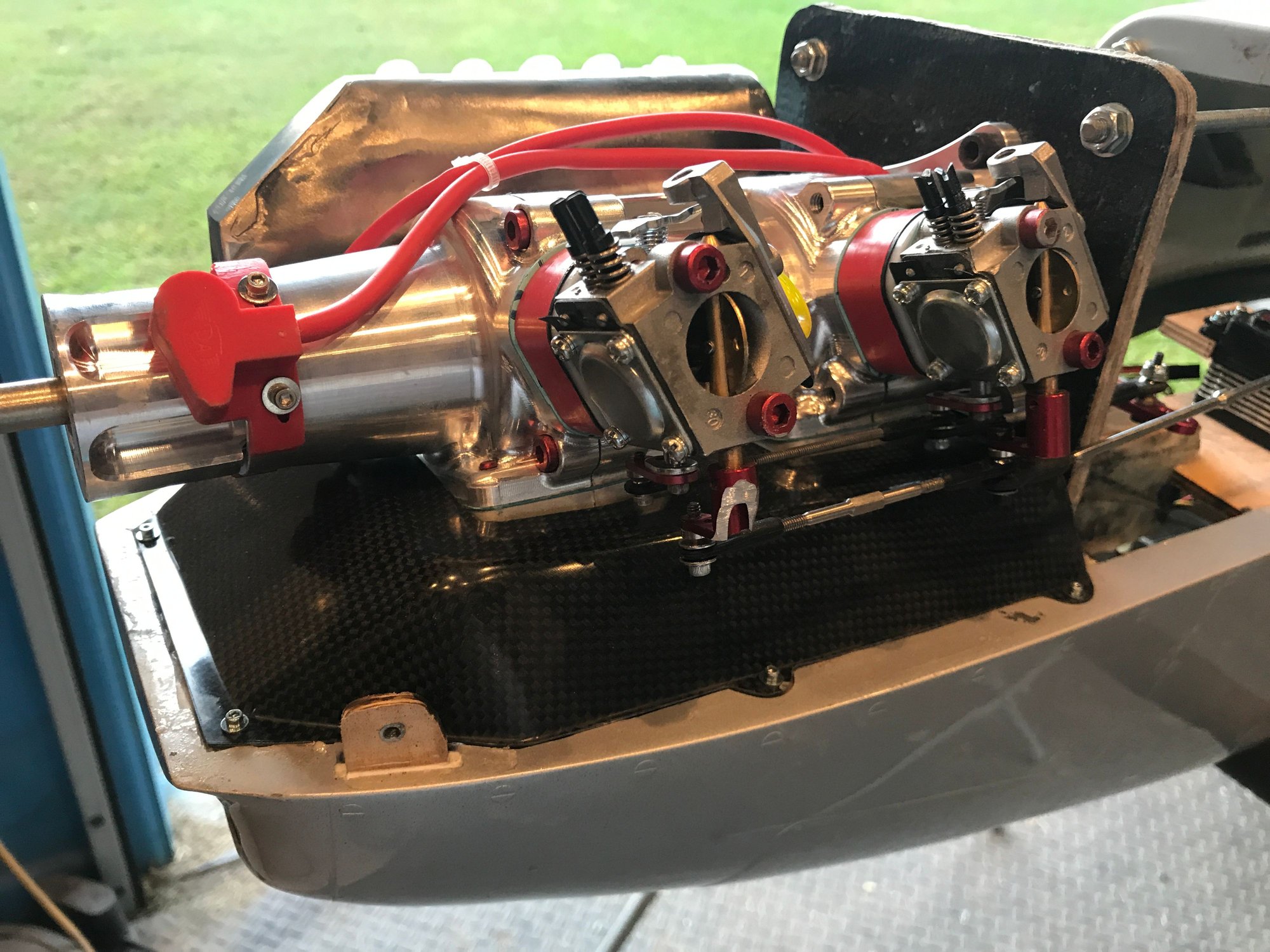
the forward carburetor choke arm has to be machined down to help clear the left cowl.
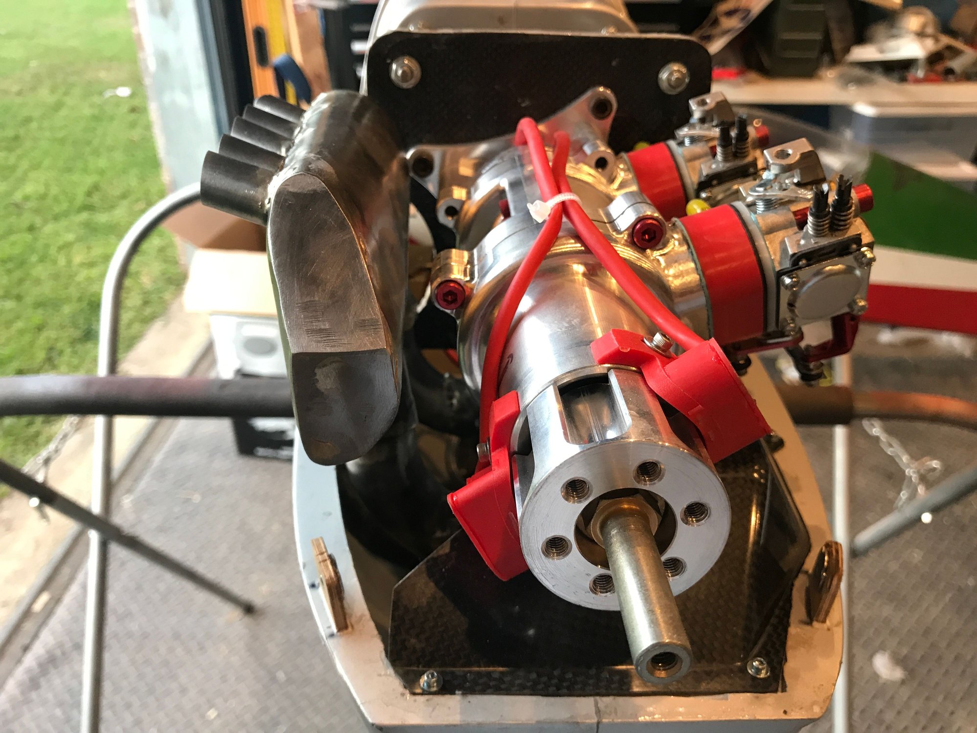
Plenum in place for the baffling
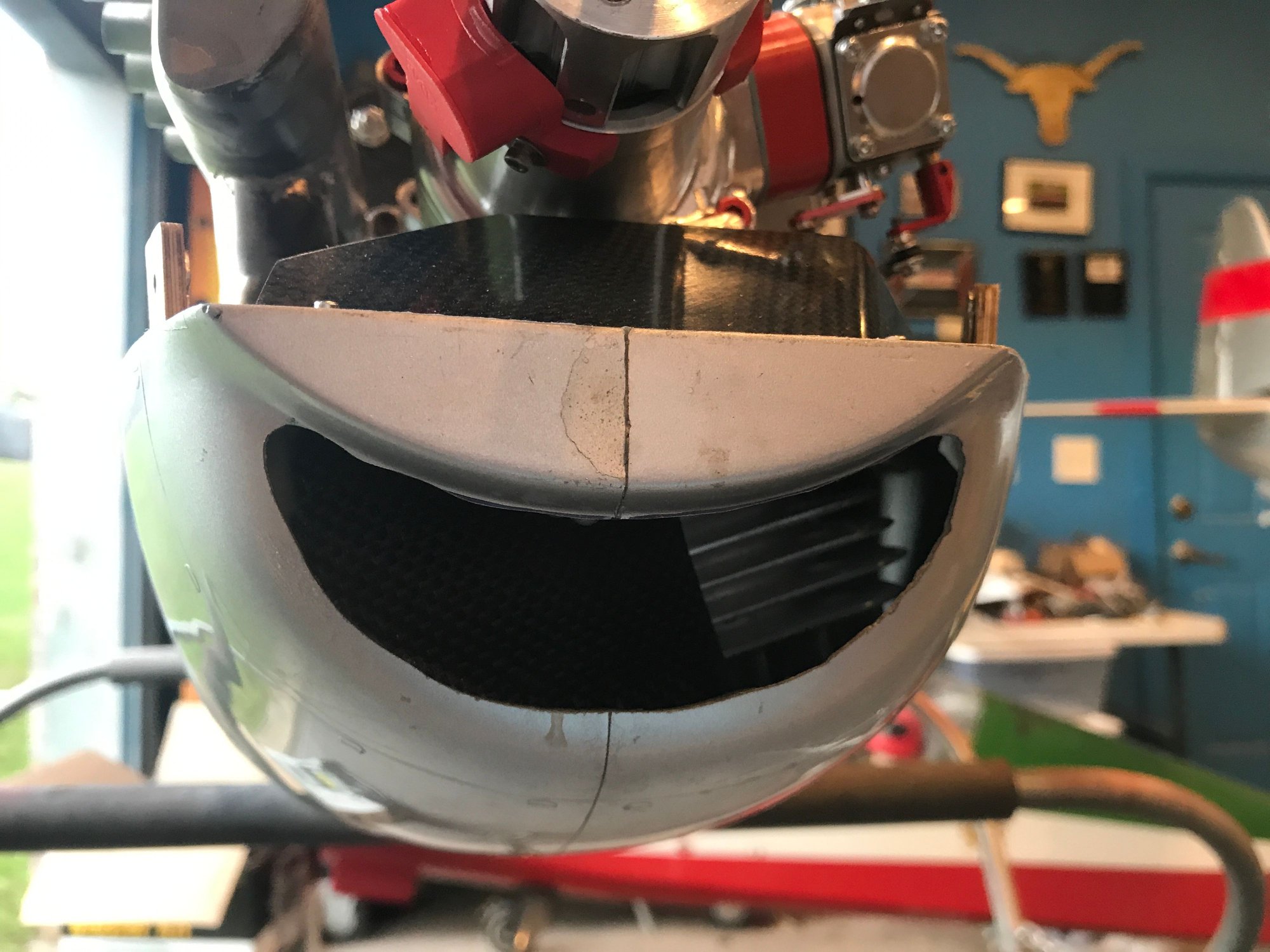
front air entry with the air diverter plater in place


ignition units. The cylinders fire at 180 from each other.
DA 100 inline, baffling shroud is also installed.
the forward carburetor choke arm has to be machined down to help clear the left cowl.
Plenum in place for the baffling
front air entry with the air diverter plater in place
ignition units. The cylinders fire at 180 from each other.


 10-26-2020, 02:42 AM
#173
My Feedback: (1)
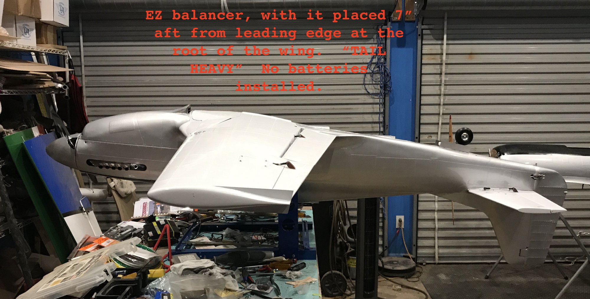
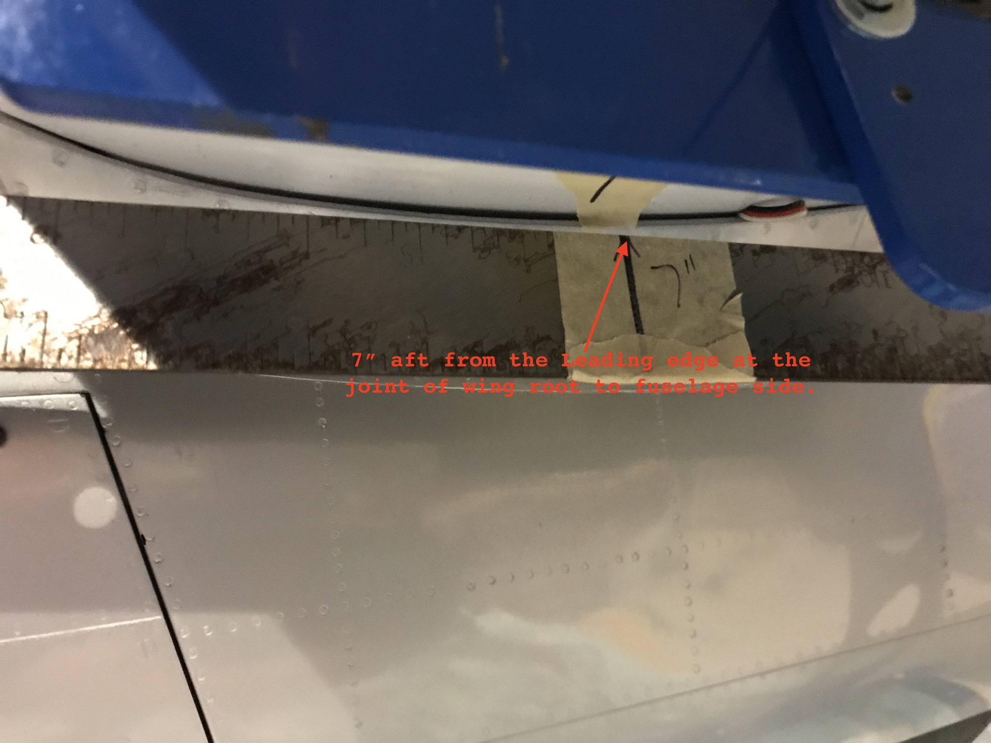
question to you all, how do you determine where the 7" back from leading edge of the root of the wing should be??
is this with wings separated and looking at the root of the wing?
or is this based on the fuselage side?

is this with wings separated and looking at the root of the wing?
or is this based on the fuselage side?
Last edited by orthobird; 10-26-2020 at 02:46 AM.
10-26-2020, 06:49 AM
#174
Thread Starter
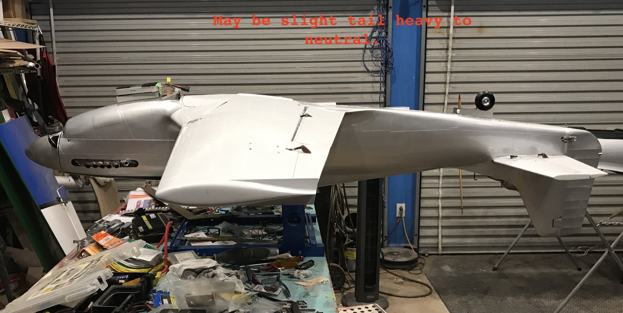
It's looking really good. I like that you have so much room under front cowl compared to my kolm takes up the whole this. I bet you'll be 10 lbs lighter then my setup. Once done, I'd like to know dry weight of the plane.
ROb
ROb


