


1/7 Scale Blackburn Buccaneer All Composite Scratch Build


 - relaying the build chronologically.

 10-17-2018, 06:47 PM
#29
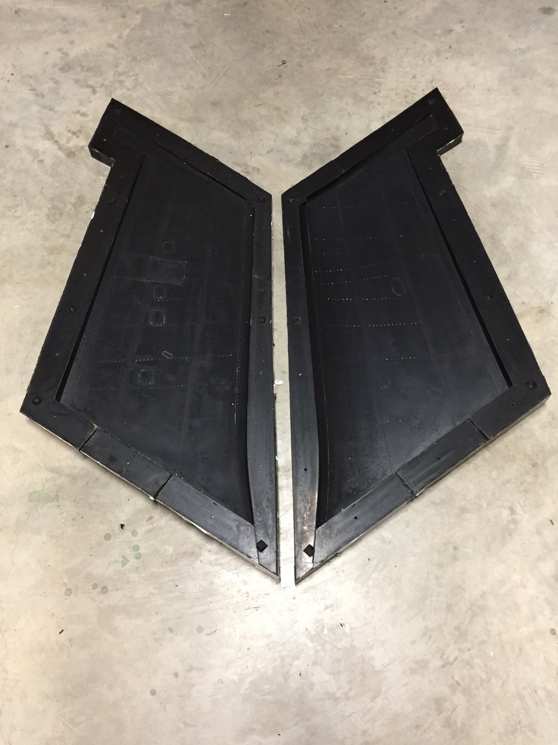
Next up were the wings.
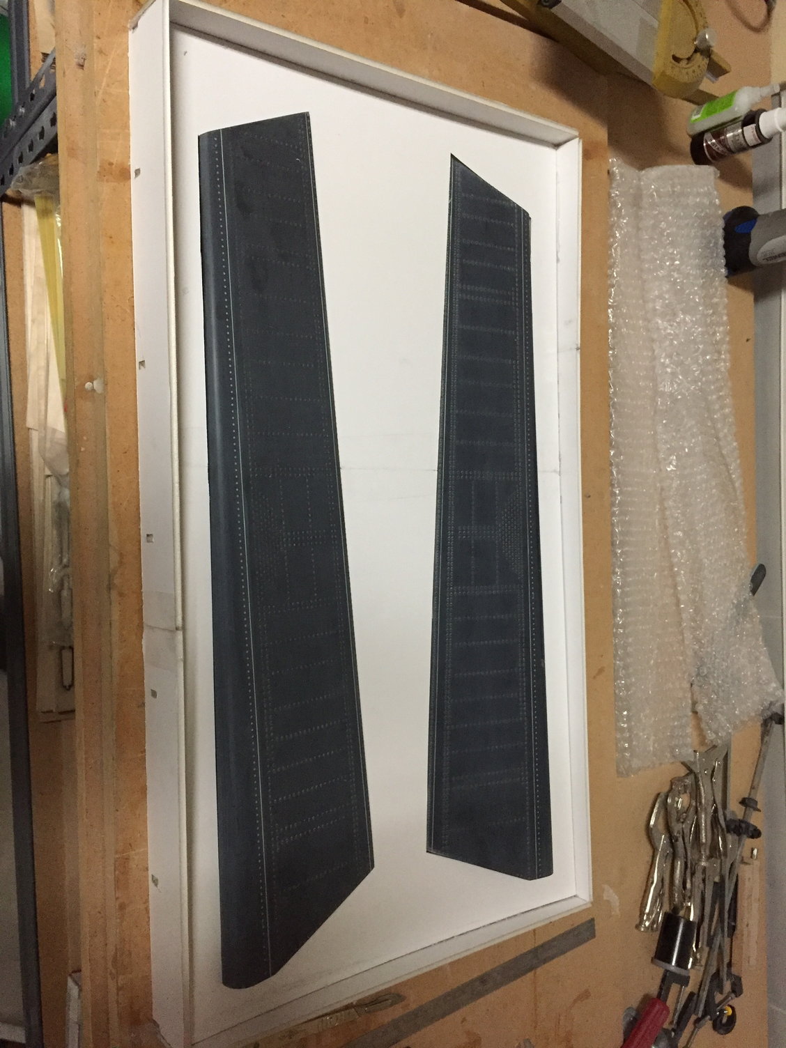
I made the wings separate at the scale wing fold line and worked on the outer wing panels. Like the tailplane these were of a traditional built up sheeted construction.
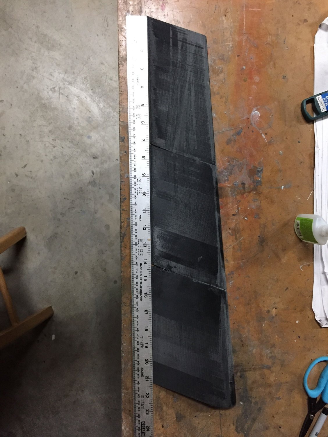
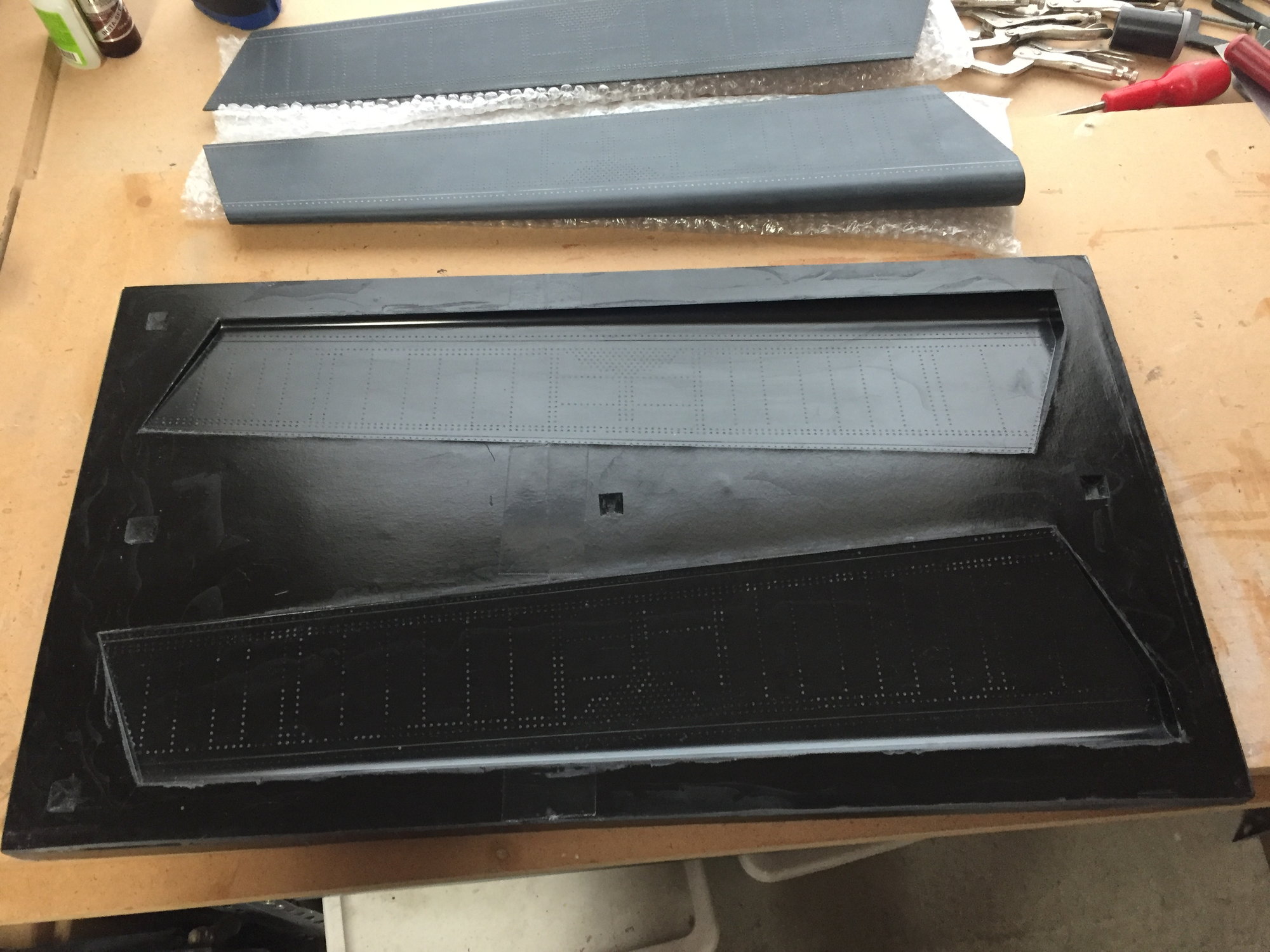
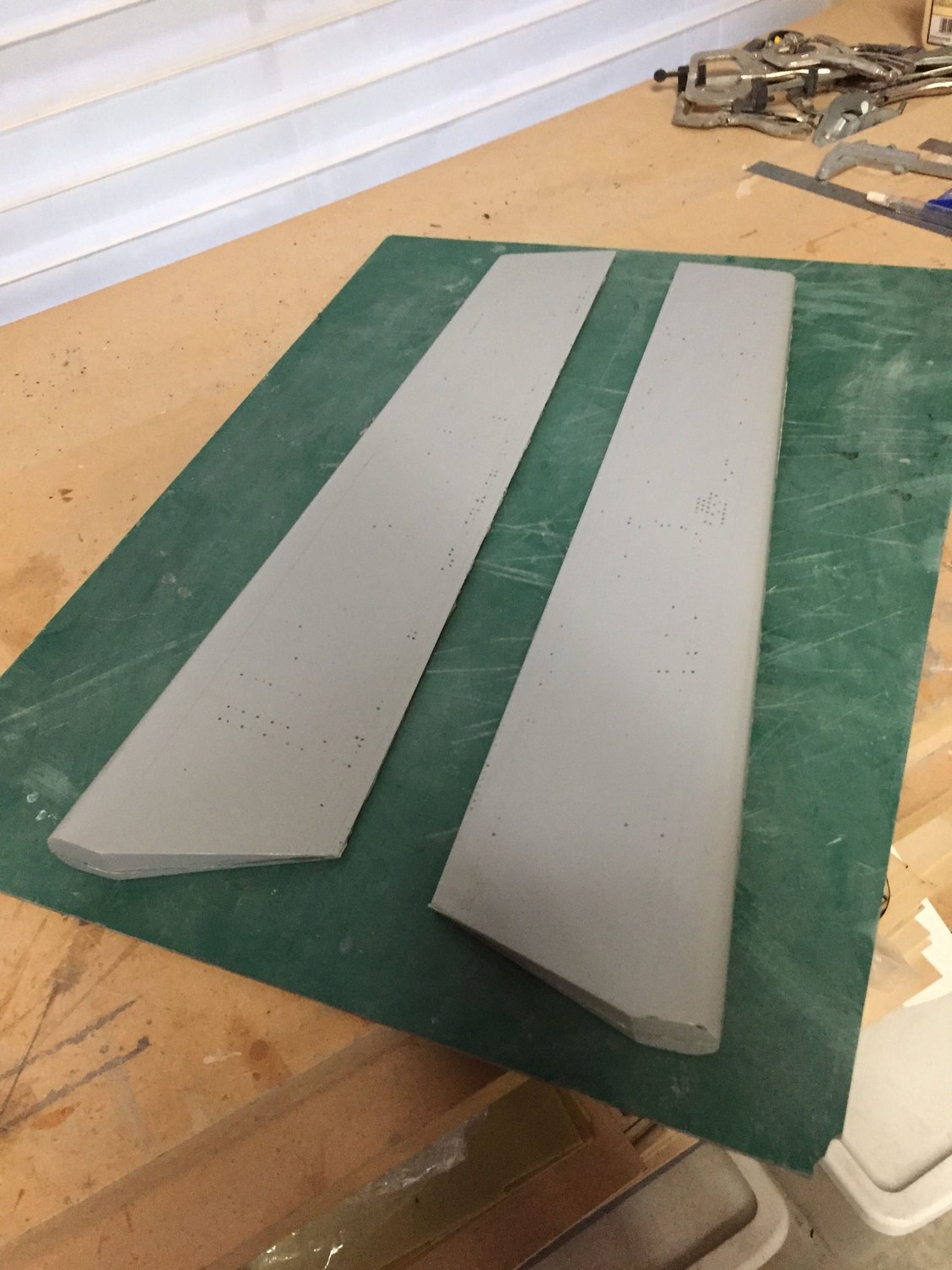
With the wing designed in CAD, I separated the flaperons and 3D printed them, split into 3 pieces to fit the printer build space.
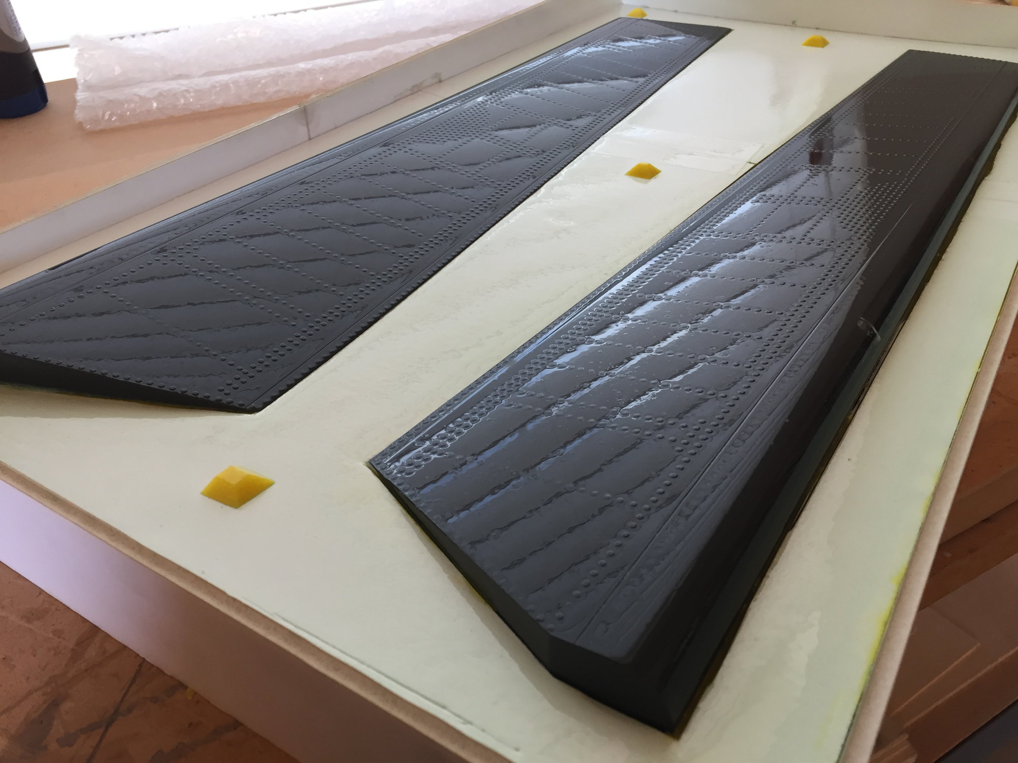
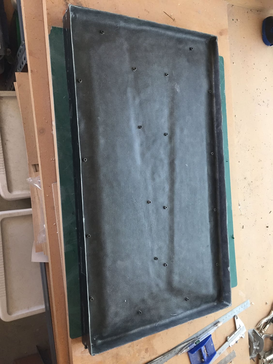
Once glued together, the flaperons were glassed to give a consistent surface and to reinforce the CA joints before getting a Duratec surface coat.
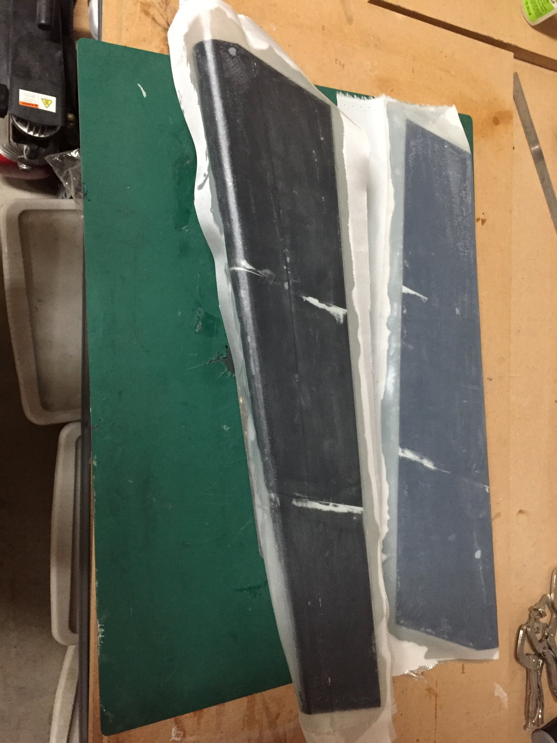
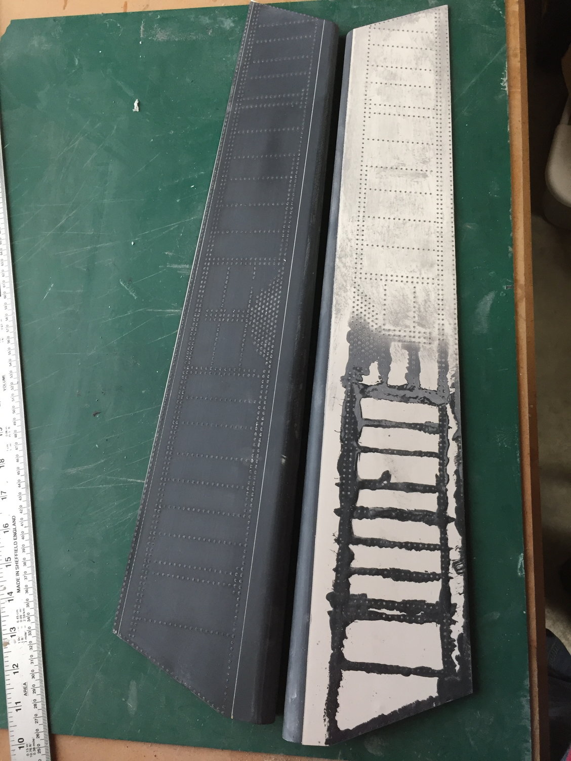
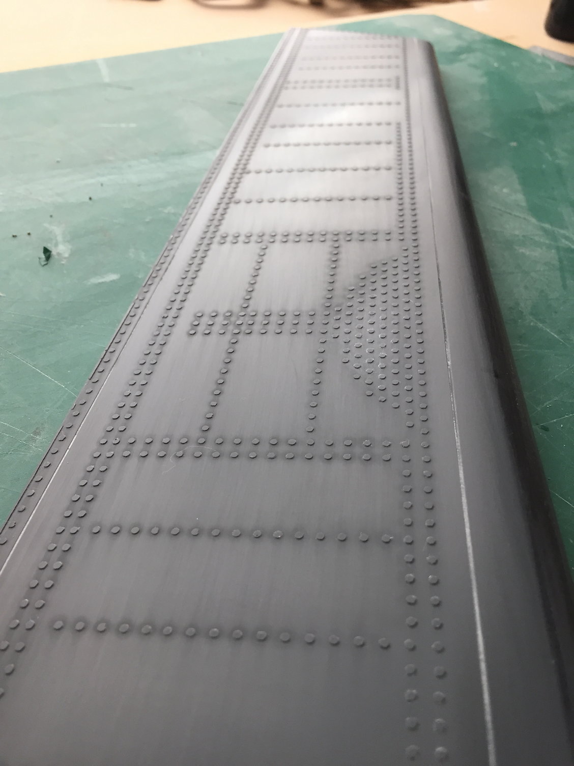
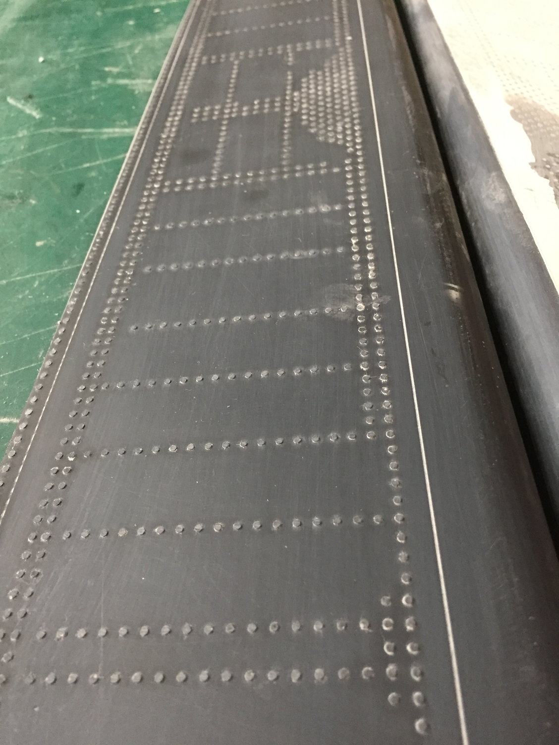
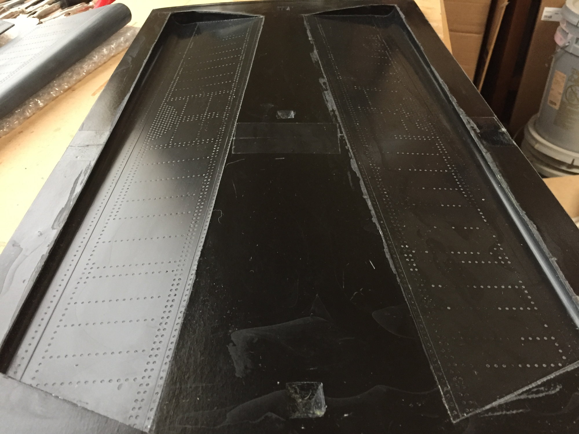
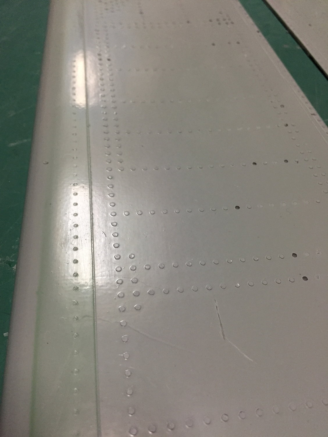
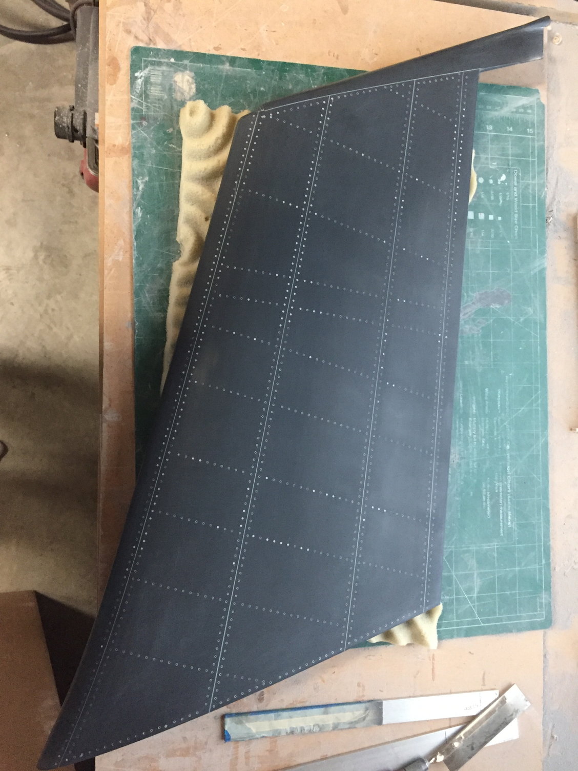
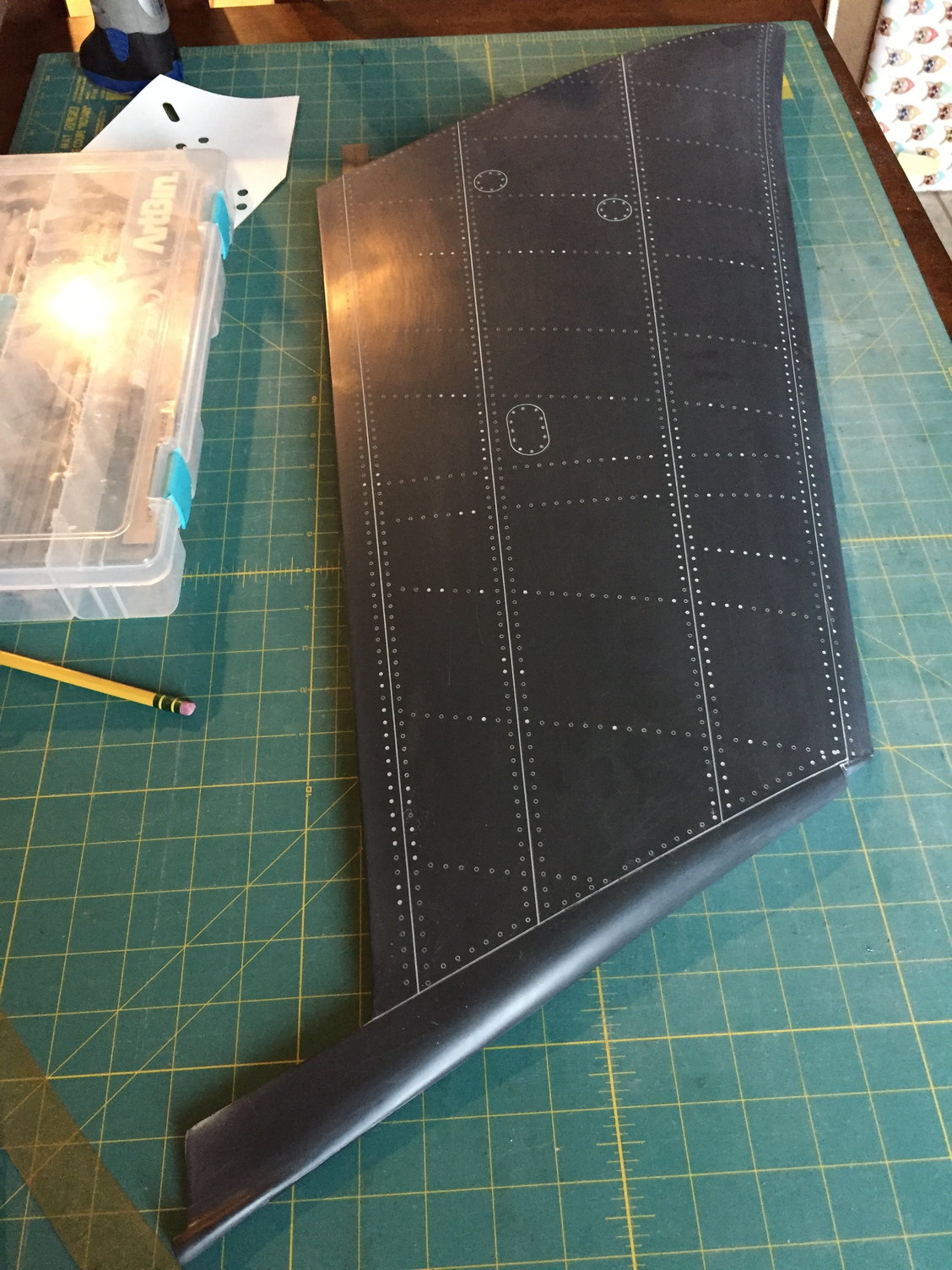
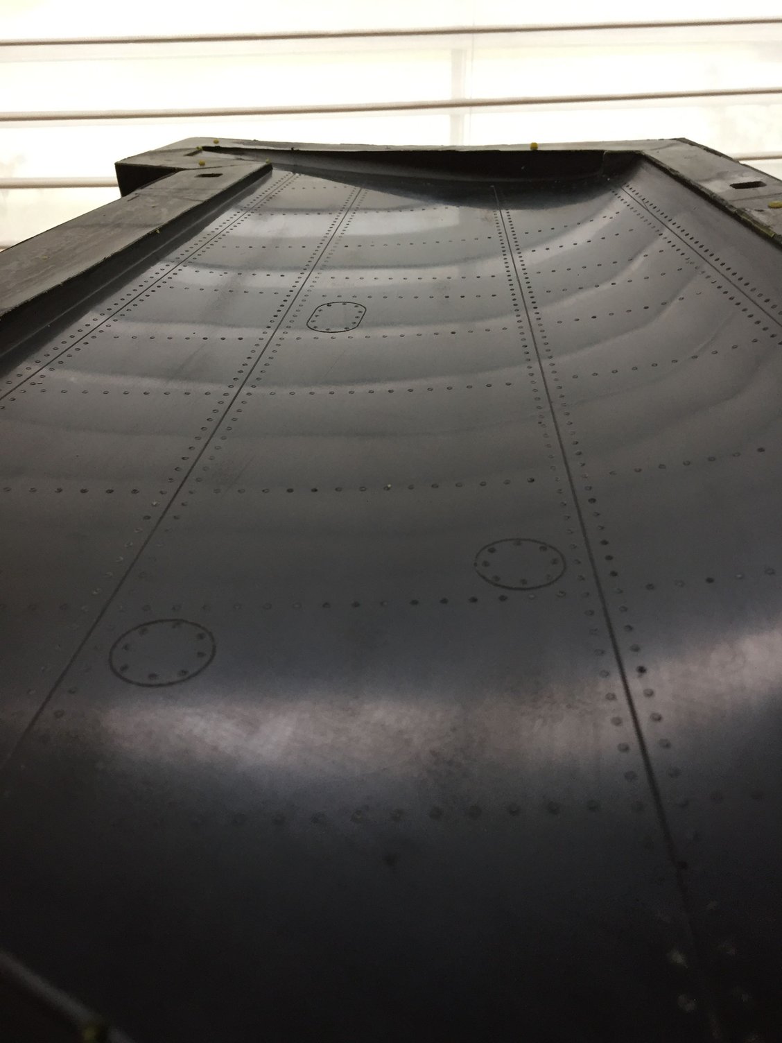
The full scale has raised rivets on the flaperon, so a few head scratches working out how to reproduce the rivets. I eventually settled on laser cutting a rivet pattern into a thick sheet of self-adhesive stencil paper, applying the stencil to the flaperon surface and then filling the holes with Duratec surface coat. Once dry, the excess primer was sanded off and the stencil paper removed. An instant set of raised rivets. The only downside is that the rivets are raised but flat topped, not domed, but hopefully once painted the difference will be negligible.
I made the wings separate at the scale wing fold line and worked on the outer wing panels. Like the tailplane these were of a traditional built up sheeted construction.
With the wing designed in CAD, I separated the flaperons and 3D printed them, split into 3 pieces to fit the printer build space.
Once glued together, the flaperons were glassed to give a consistent surface and to reinforce the CA joints before getting a Duratec surface coat.
The full scale has raised rivets on the flaperon, so a few head scratches working out how to reproduce the rivets. I eventually settled on laser cutting a rivet pattern into a thick sheet of self-adhesive stencil paper, applying the stencil to the flaperon surface and then filling the holes with Duratec surface coat. Once dry, the excess primer was sanded off and the stencil paper removed. An instant set of raised rivets. The only downside is that the rivets are raised but flat topped, not domed, but hopefully once painted the difference will be negligible.


 10-19-2018, 01:38 AM
#37
Hello Paul,
Thanks for your feedback. Its a big job you are undertaking and wish you all the best. I did a full composite prop plane and so I know what this work entails. I also think that, like I did, too much vacuum may pull the details away (rivets especially). I have not had time to play around to see what the optimum vacuum pull is so that all the details will remain there. Its a balance between vacuum and epoxy retention (whilst retaining most of the detail work). Anyway it is a great project. I always shyed away from the Buccaneer as I have no metal engineering capabilities to make the scale retracts and its retraction process since the main strut "shrinks" before retracting in the wheel well.
Again, all the best and thanks for your reply.
Reuben
10-19-2018, 03:34 AM
#38
Reuben,
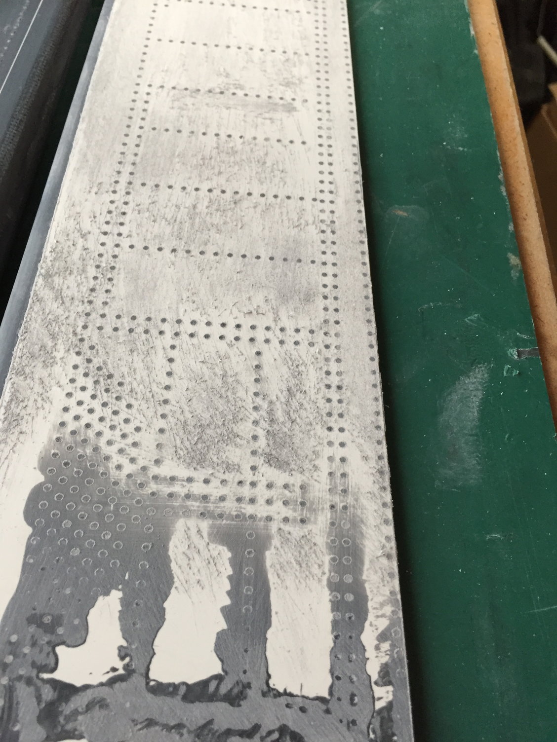
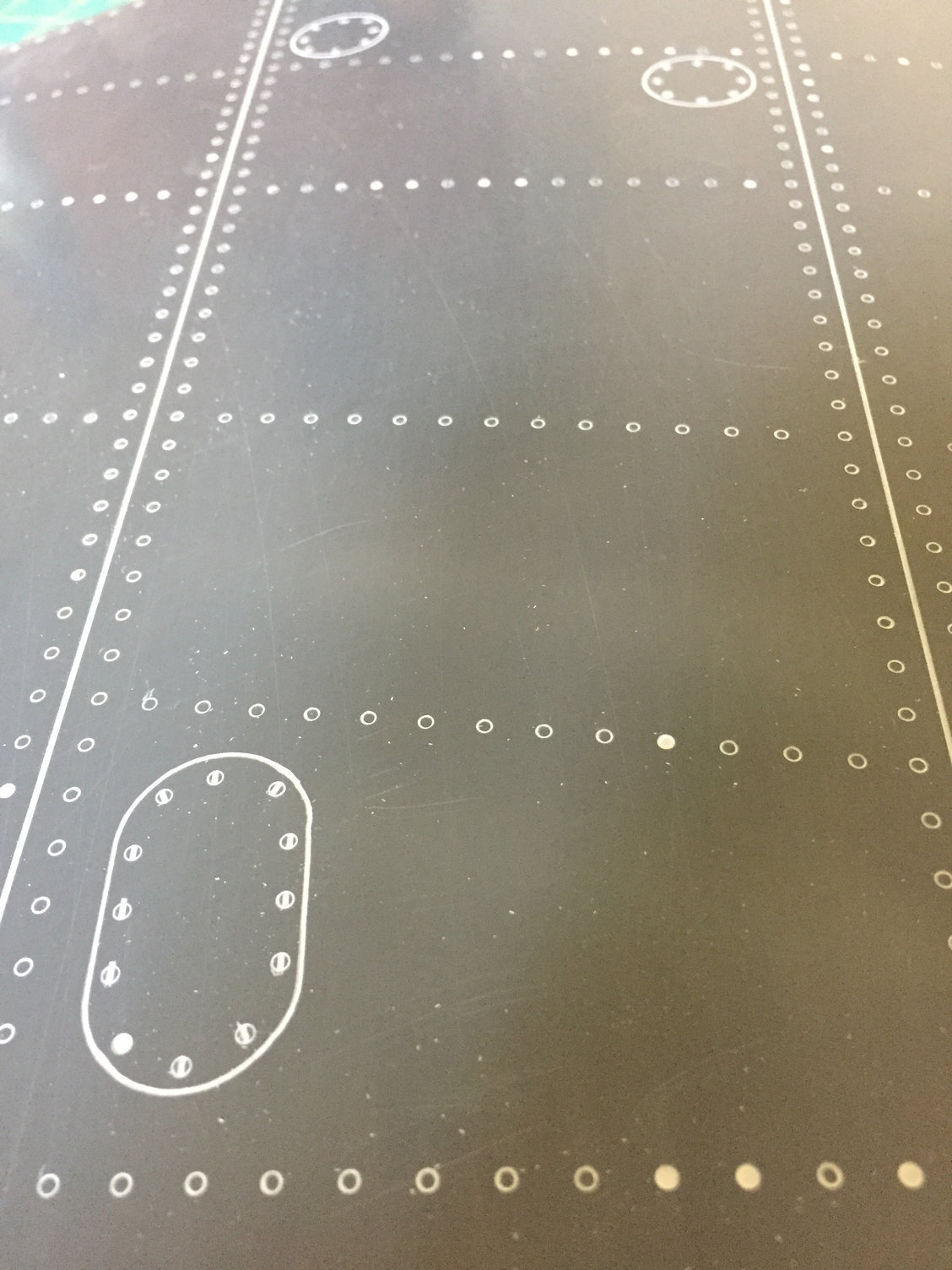
Thanks - for the most part I only 'lost' the primer part of the rivets. Most of the actual rivet is still there on the ones that look like they are missing.
Yes, the retracts are a challenge unto themselves. I'll get to describing them soon, but I believe that I have a solution.
Paul
Thanks - for the most part I only 'lost' the primer part of the rivets. Most of the actual rivet is still there on the ones that look like they are missing.
Yes, the retracts are a challenge unto themselves. I'll get to describing them soon, but I believe that I have a solution.
Paul
10-19-2018, 05:32 AM
#39
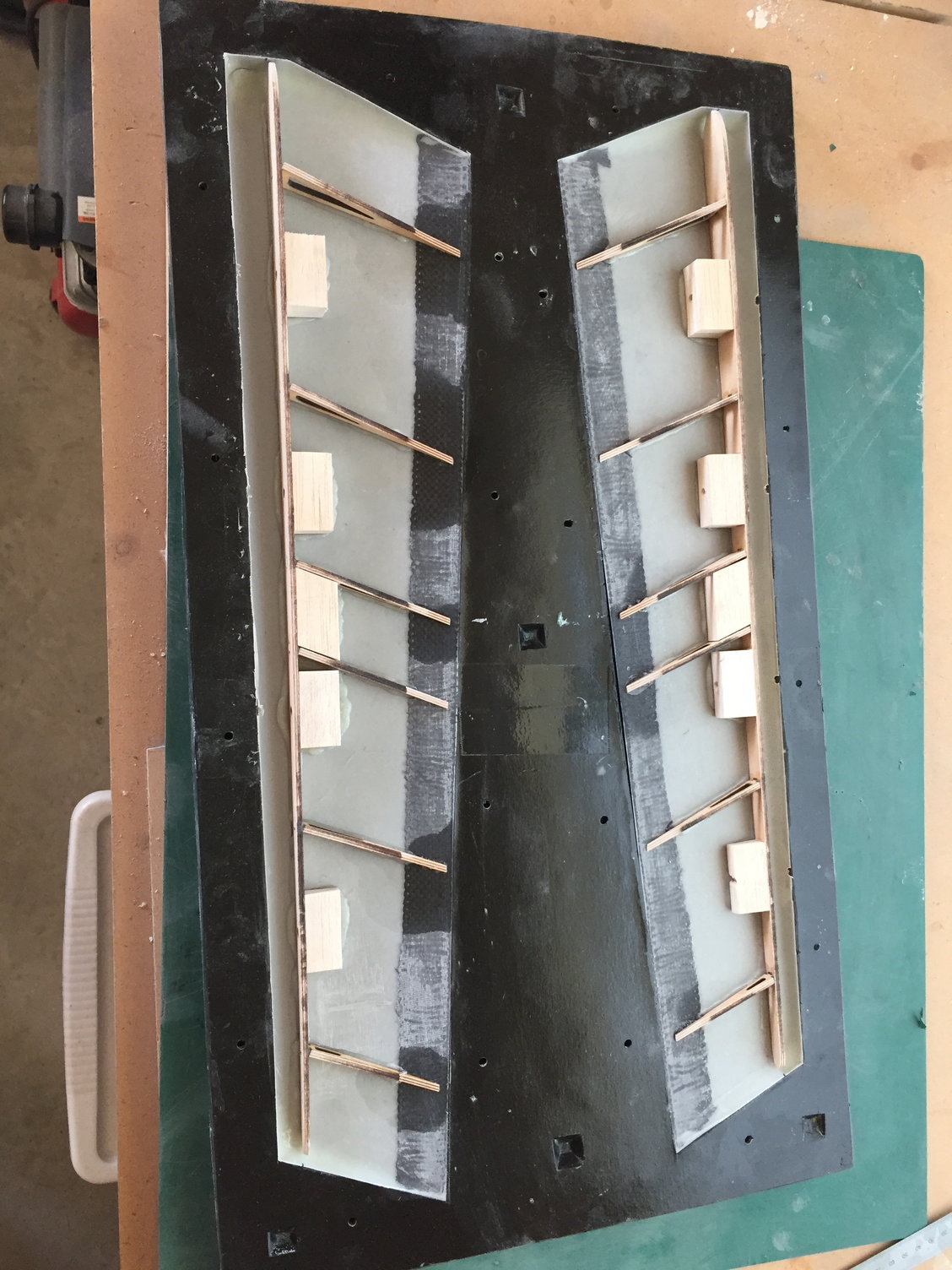
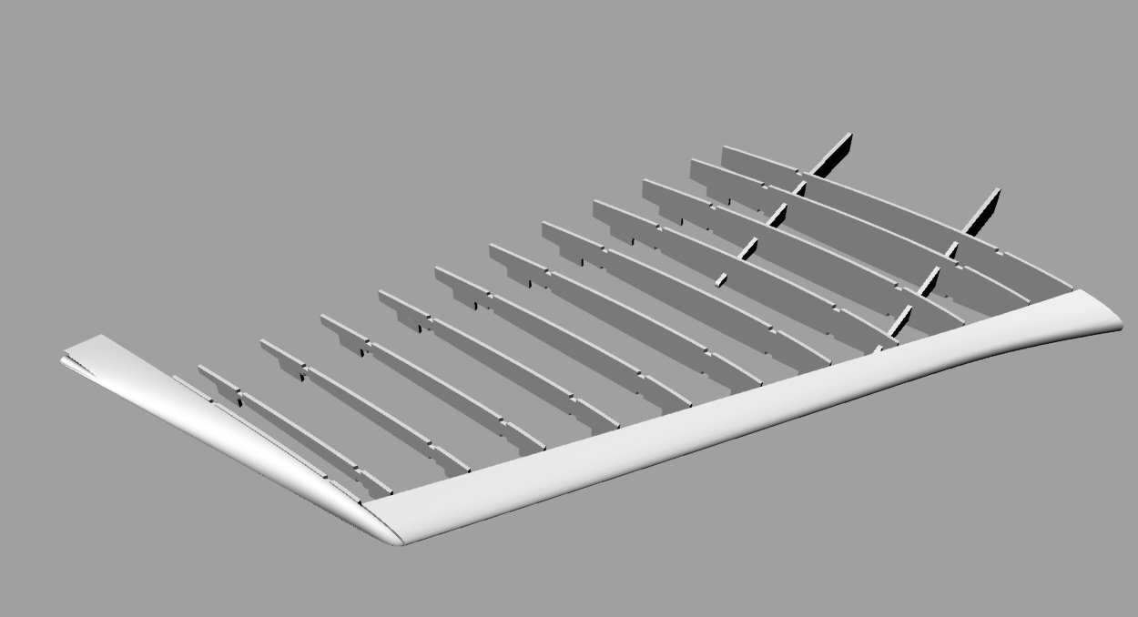
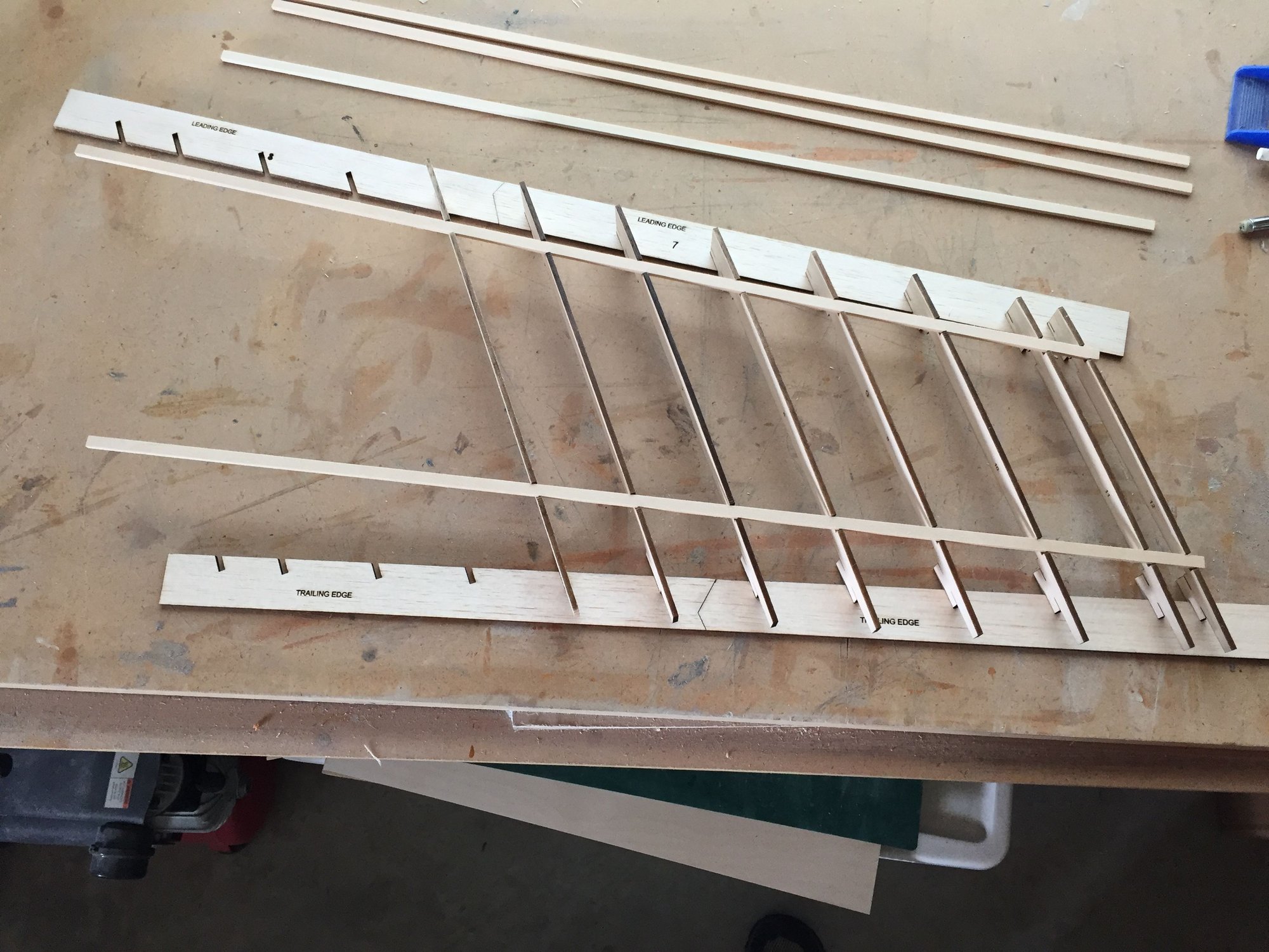
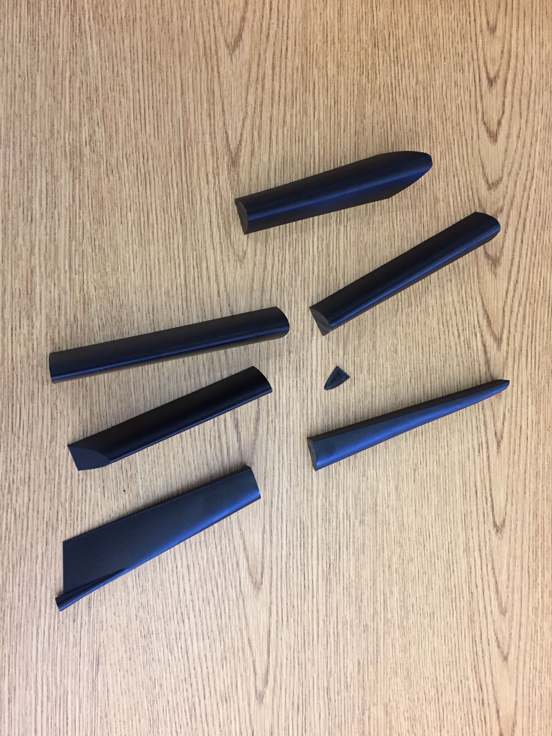
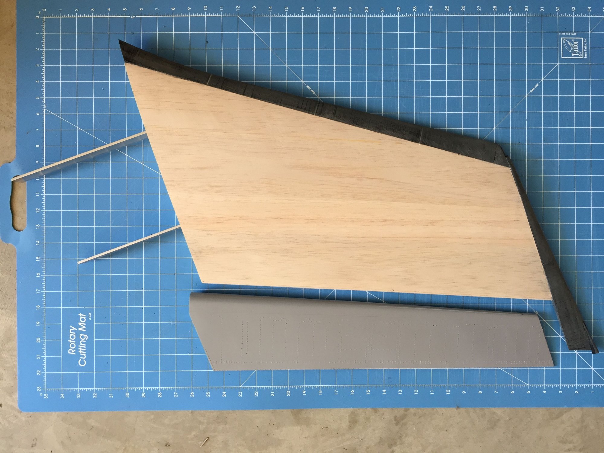
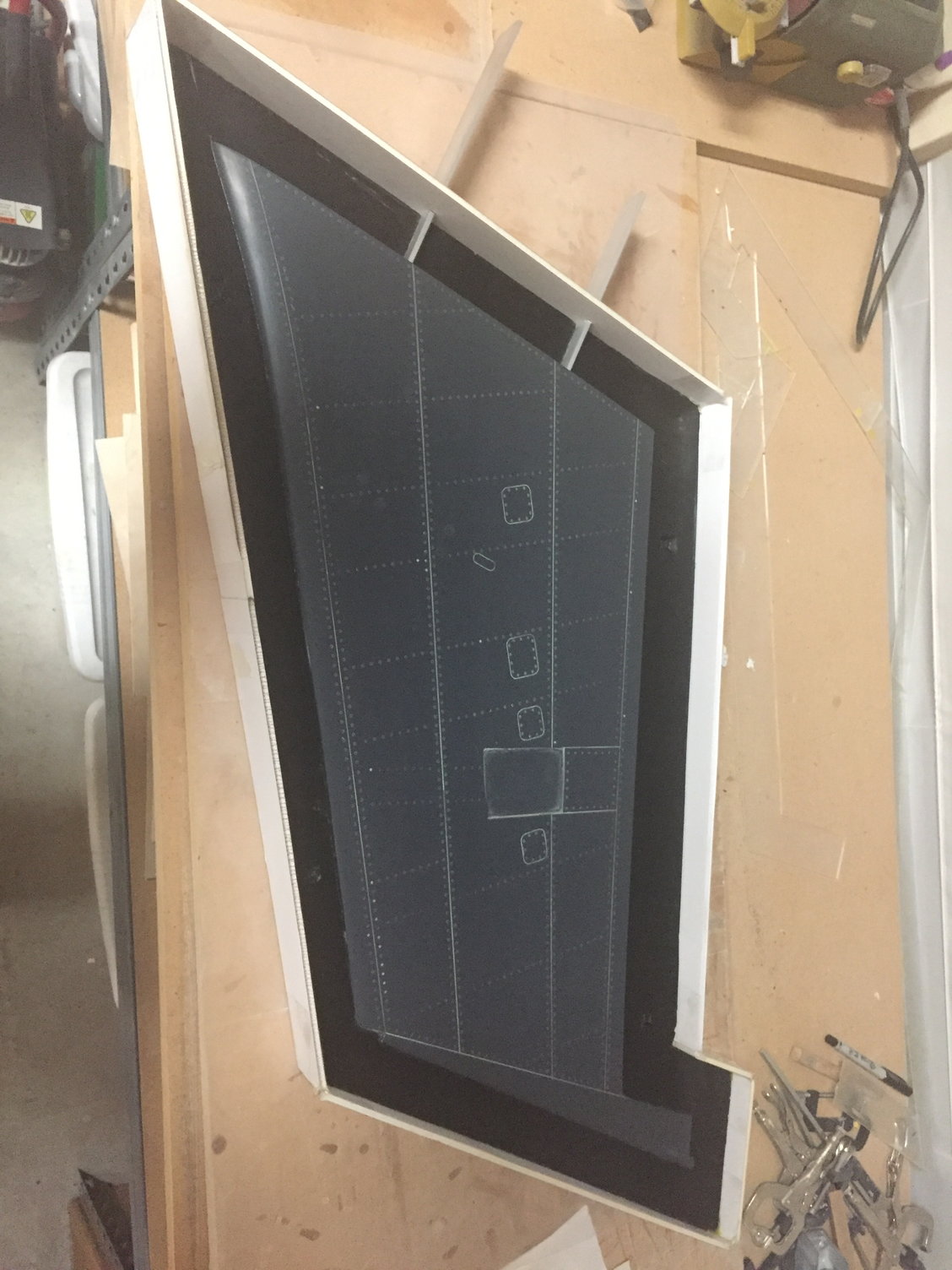
Onto the outer wings. The plug was of a traditional balsa skinned built up construction, but I decided to 3D print the leading edge and wingtip in order to capture the complex curves. The LE was split into 3 parts to fit the printer build volume. I made a cutout in the wingtip for a nav light a with a recessed edge to facilitate bonding in the clear cover.
The wing was designed with a 3deg twist (washout) along the hinge line and individual tabs on the ribs captures the correct rib alignment. I made a building jig to align all of the ribs. It was then an easy matter to glue in the 1/4"x1/8" basswood spars. No internal shear webs were used as this wing doesn't have to take flight loads. The inner ribs were cut from ply in order to be able to hold the wing joiner spars which will be used to provide alignment in the mold and during wing construction.
With the ribs being laser cut, alignment of the wing with the 3D printed leading edge was excellent and no filler was needed.
Last edited by JSF-TC; 10-19-2018 at 05:38 AM.
 10-19-2018, 05:53 AM
#41
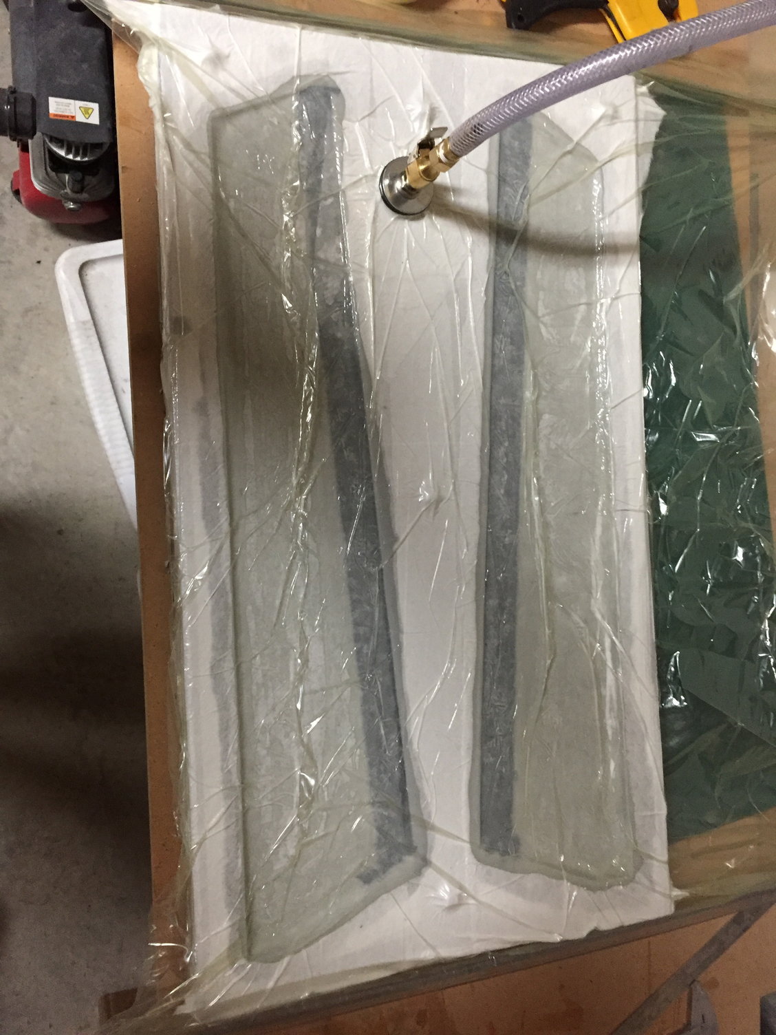
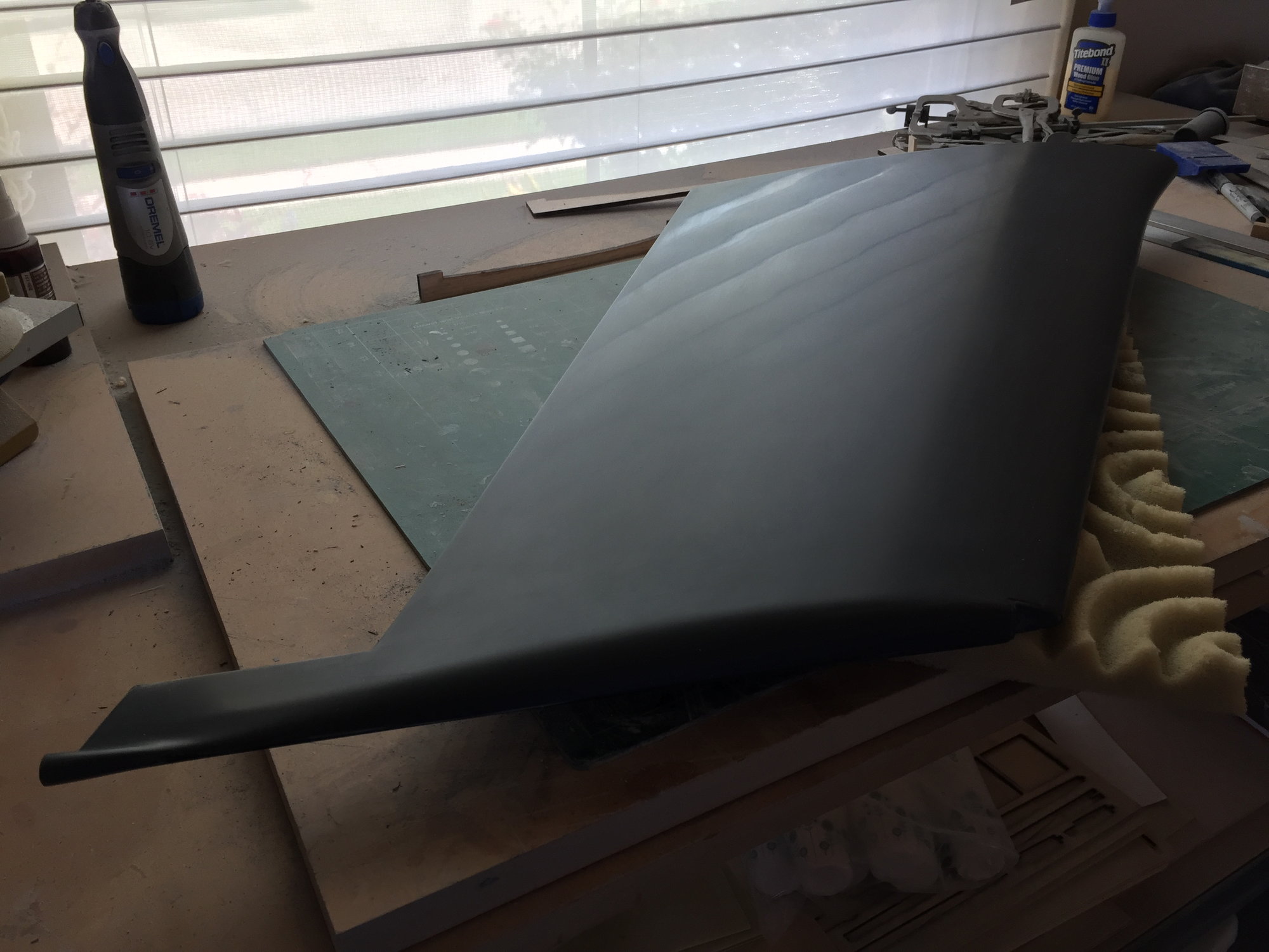
Making the wing molds, I decided to switch from wax/ PVA as a release agent and use Frekote. A much simpler process throughout, and you don;t need to remove the damaged PVA at each step. Frekote is good for a few uses before it needs to be re-applied. I sprayed on 2 coats of the Frekote and left it to dry in between. The first plug ended up with fish-eye type marks from the Frekote, so on the second wing plug after spraying on the Frekote, I wiped it down with a paper towel wetted with additional Frekote. This resulted in a mirror smooth mold surface and is now my standard technique for applying it.
Wing mold construction followed the previous process, but I decided to try using an acrylic sheet for the parting plane rather than the foam poster board, which sometimes didn't release cleanly and took a lot of work to clean up. I laser cut the parting plane acrylic sheet to match the wing shape. Not as easy to use as the foam board, but it separated cleanly and it was re-usable, the same parting plane was turned over and used for the second wing mold construction.
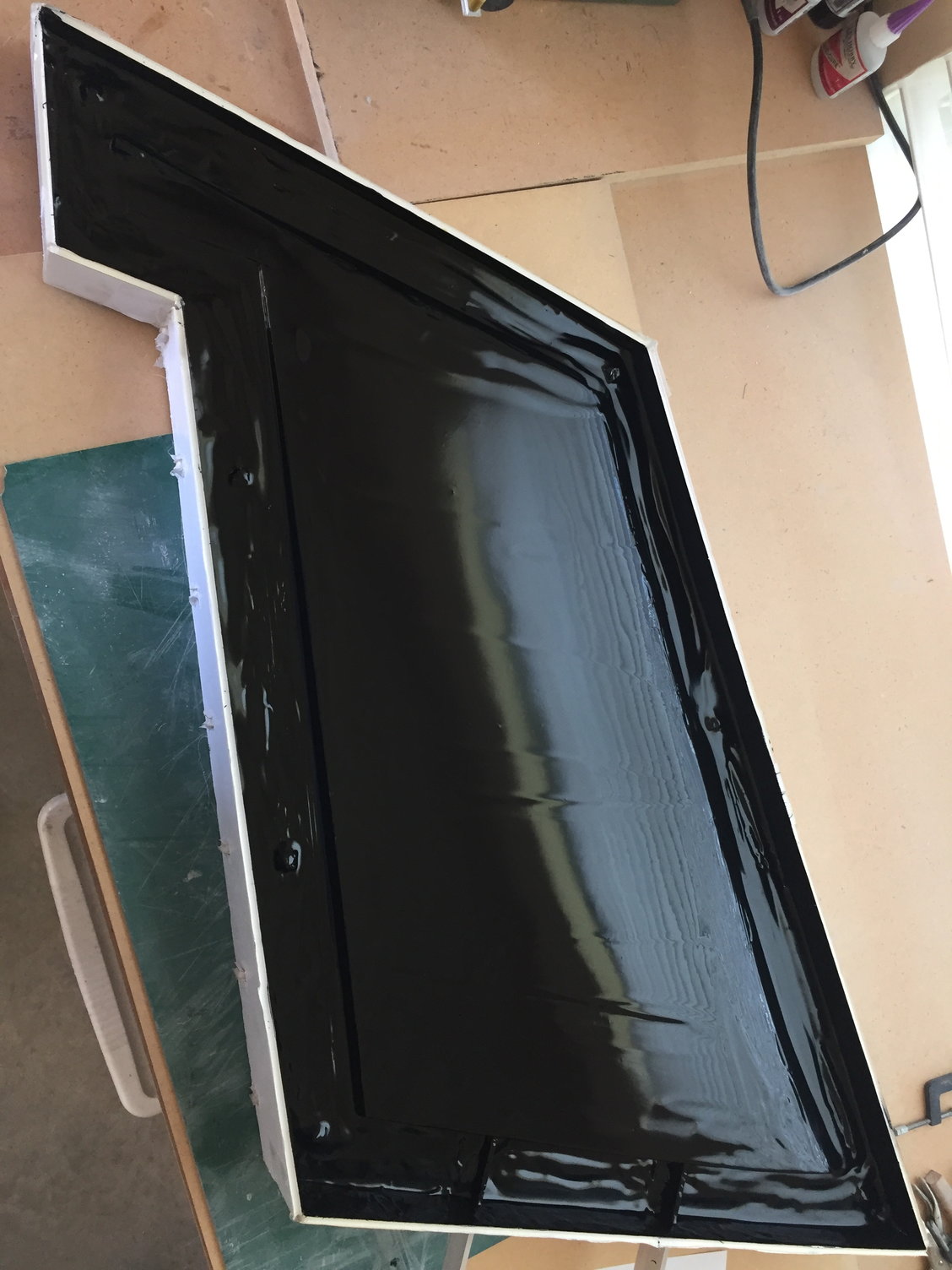
Wing mold construction followed the previous process, but I decided to try using an acrylic sheet for the parting plane rather than the foam poster board, which sometimes didn't release cleanly and took a lot of work to clean up. I laser cut the parting plane acrylic sheet to match the wing shape. Not as easy to use as the foam board, but it separated cleanly and it was re-usable, the same parting plane was turned over and used for the second wing mold construction.
10-19-2018, 06:00 AM
#42
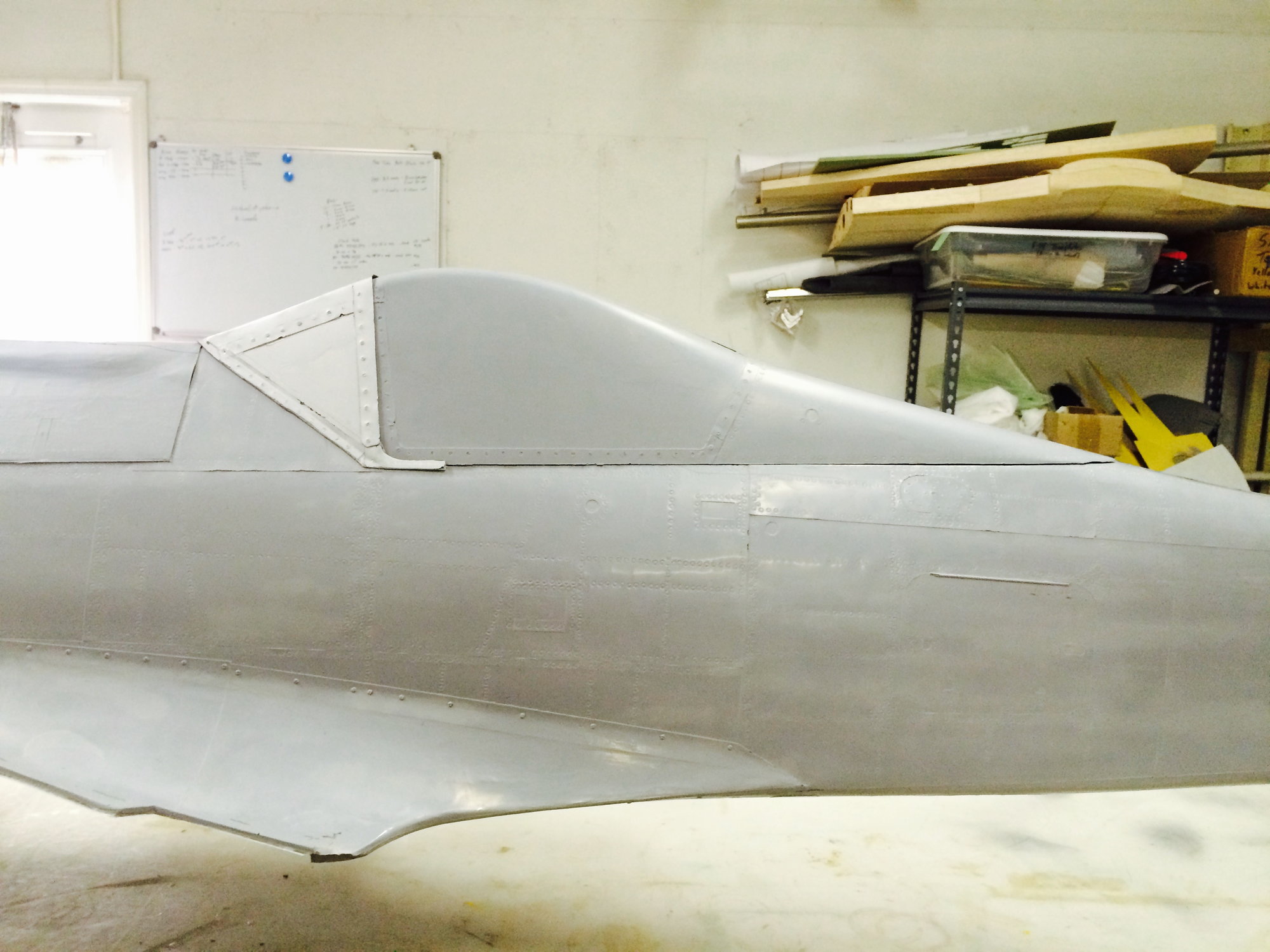
In the background I had been struggling with developing the CAD model for the fuselage. The 3 view drawings gave good info for the plan and side view outlines, but they lacked any info for cross-sections. The data I managed to find resulted in a very poor model with lots of wrinkles. Multiple attempts never got to the point that I was happy to freeze the design.
I bought a 1/72 scale plastic kit of the Buccaneer as an aid. With the fuselage partially built, a friend got me access to UT Arlington's Fab Lab where they have a high resolution 3D scanner.
It was finally starting to have a passing resemblance to a Buccaneer.
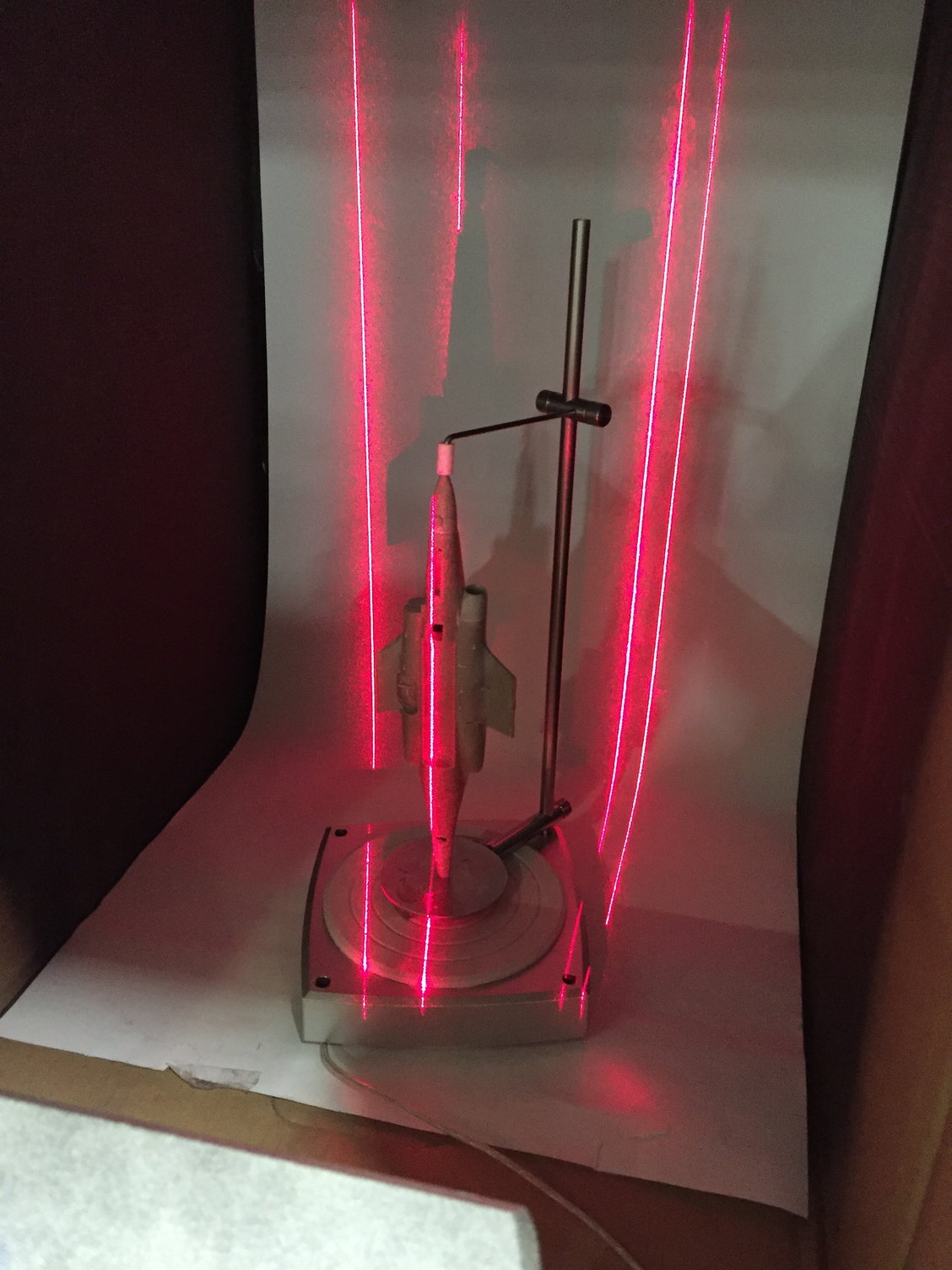
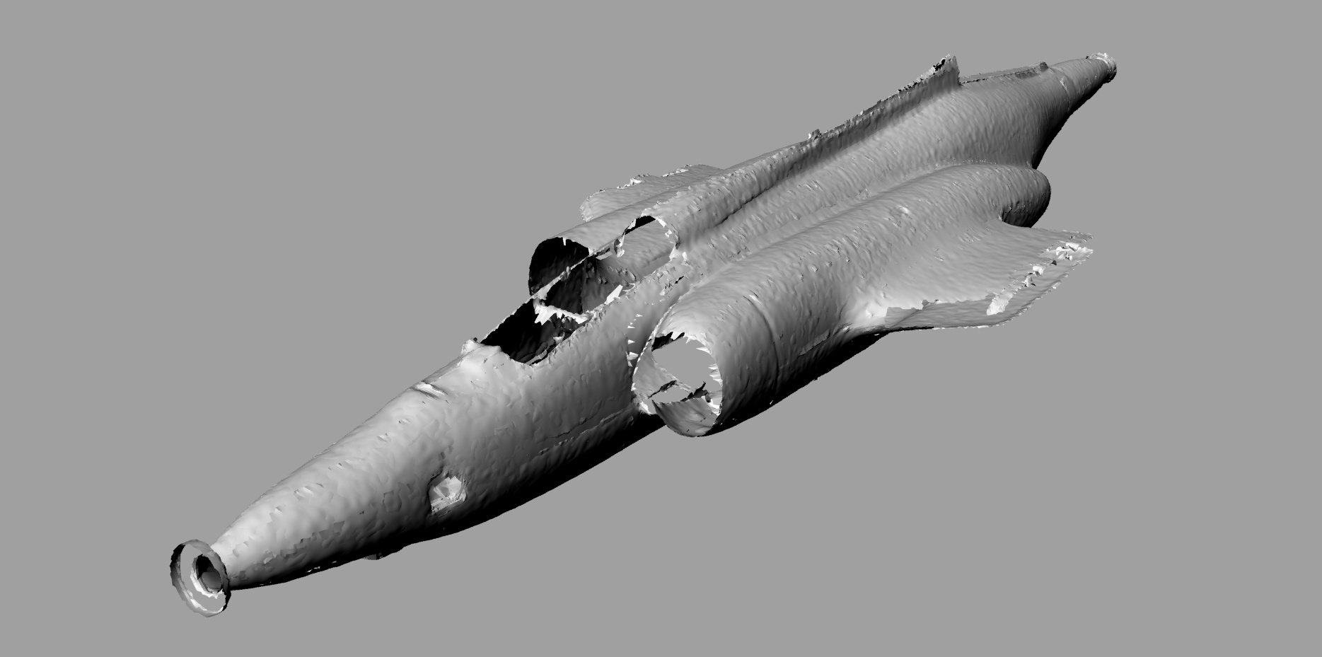
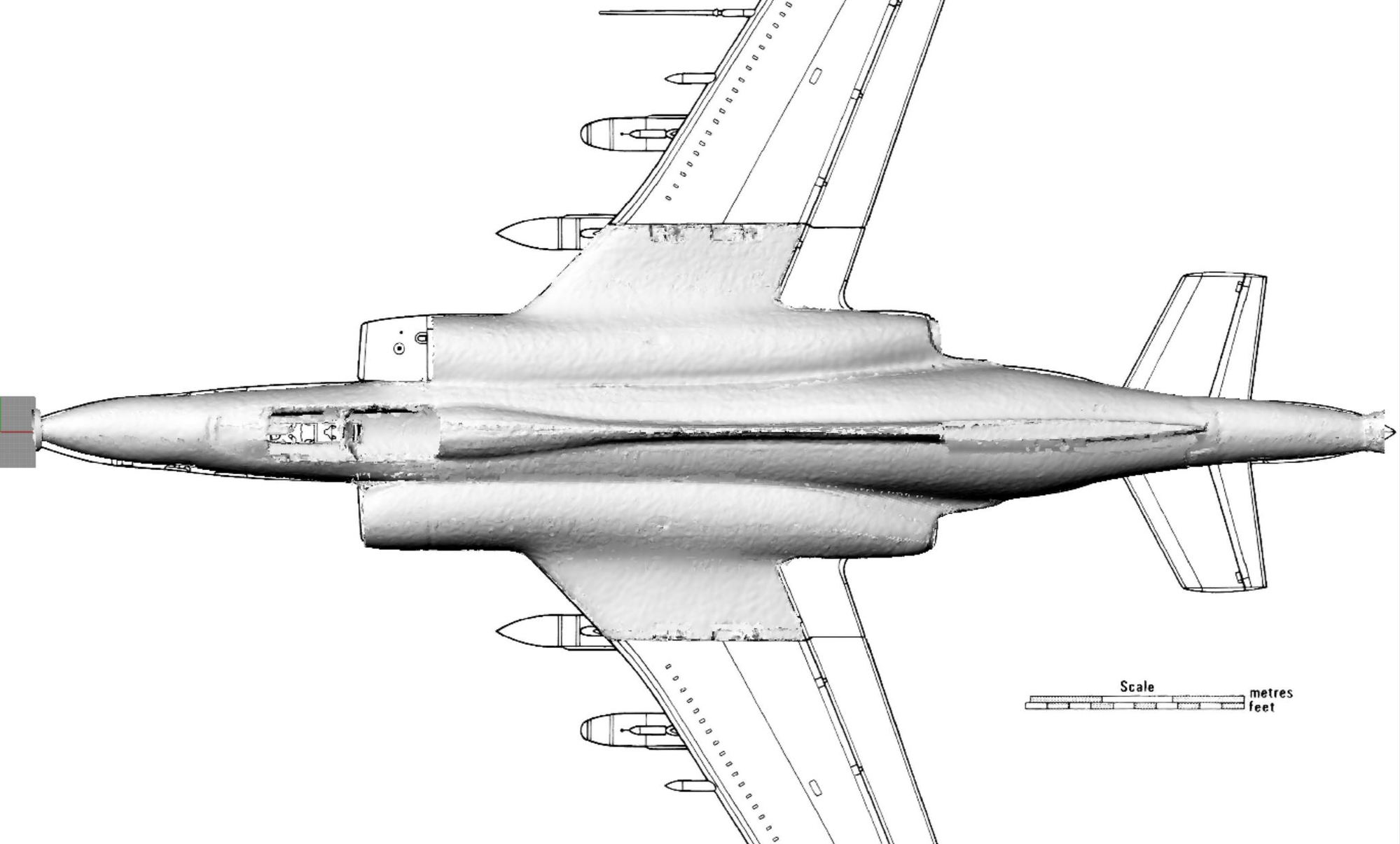
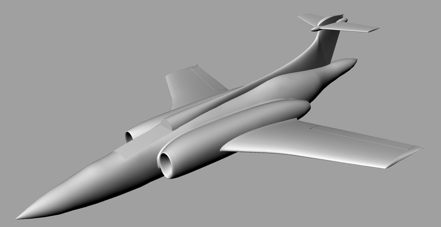
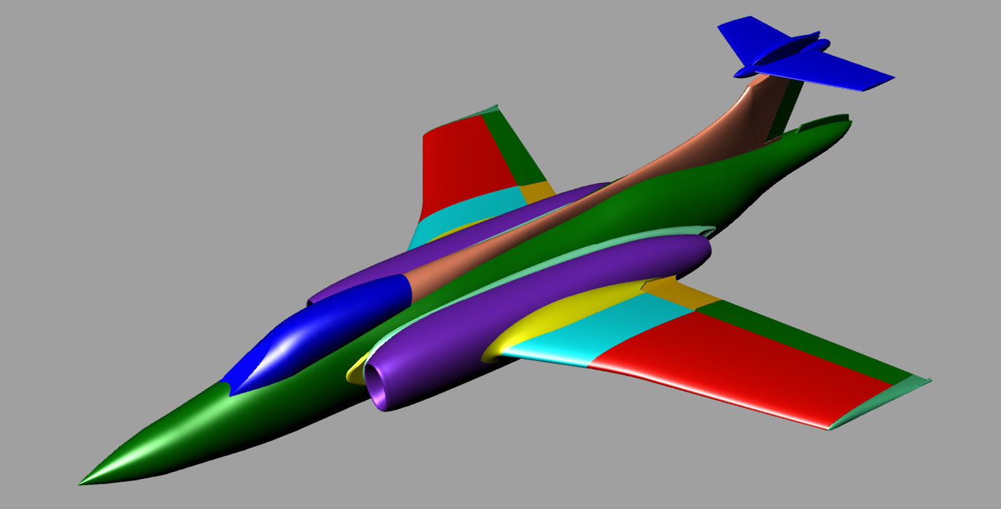
This proved to be the turning point in developing a CAD model I was happy with. With the 1/72 model fuselage scanned, I was able to pick off some good cross-section data and build a smooth fuselage model. With that milestone complete I was able to add in the nacelles and inner wing.
I bought a 1/72 scale plastic kit of the Buccaneer as an aid. With the fuselage partially built, a friend got me access to UT Arlington's Fab Lab where they have a high resolution 3D scanner.
It was finally starting to have a passing resemblance to a Buccaneer.
This proved to be the turning point in developing a CAD model I was happy with. With the 1/72 model fuselage scanned, I was able to pick off some good cross-section data and build a smooth fuselage model. With that milestone complete I was able to add in the nacelles and inner wing.
Last edited by JSF-TC; 10-19-2018 at 06:05 AM.
10-19-2018, 08:58 PM
#44

Looking good!
for your parts with alot of surface details, put a layer of 1/2 or 3/4oz glass down and allow it to go �green� before you do the skin layup and put it under vacuum. That�ll retain all the surface detail and you wont gain any significang weight.
10-22-2018, 09:33 AM
#45
Thomas,
Thanks - Impressive FW190 - your own design?
I have been using a polyester surfacing veil as my first layer in building the parts and getting good detail reproduction, but I have not been letting the resign go 'green' before continuing with the woven cloth layers. It has been doing a decent job of blocking the fabric weave print through, although letting it set to the 'green' stage may improve the end-result even more.
Paul
10-22-2018, 11:14 AM
#46

Great thread, this and the F-105 thread have restored my faith in man.
I agree, the use of CAD accurate, laser cut mold boards is a game changer. What surface prep do you do on the foam boards? I have tried some tests (1/100000 of what you are doing by far) and I wanted to use gatorfoam (ultra board), which is basically like foam board except one side is polystyrene plastic. We could not get it to cut well with a laser, but maybe you will have more luck? I think it could be made to work if the laser system were tweaked enough......it does not need much prep, just PVA (did not try freekote this time, I used it years ago with success).
Also, can you show any pictures of your printer? Like how did you align those printed leading edges with the print bed? Any issue with warping? The combination of a built up CAD wing with printed leading edges is unreal.
10-22-2018, 11:38 AM
#47
Matt,
Thanks for the comments. This project has really invigorated my enjoyment with the hobby. I'm almost enjoying the building part more then the flying right now. It can get extremely absorbing.
I've been using the foam board from Hobby Lobby/ Michaels. It appears to be paper coated and is 5mm thick. It cuts well on the laser cutter in one pass, but the foam undercuts a bit due to the heat. Not an issue as the gel-coat only gets in contact with the paper surface. I use a hot glue gun to join all the parts together and seal any foam board joints with parcel tape. Any gaps between the plug and parting plane get filled with a standard molding wax filler.
Both wax/ PVA and now Frekote work well on it, although if you do not use enough it can be a pain to remove afterwards as the paper tends to stay on the gelcoat more than on the foam board, so you end up having to scrape it off in pieces. I've now settled on 3 coats of Frekote, sprayed on and then wiped smooth, and the foam board separates relatively cleanly.
I have not tried the plastic coated foam board.
I'll post a picture of my printer later, but I just printed the leading edges standing on end (growing span-wise vertically off the print bed) and split into 3 parts to fit the printer. No issues with warping. I used ABS initially but have now switched to PETG due to warping/ cracking issues with ABS on larger parts.
Paul
10-22-2018, 07:53 PM
#48
Thomas,
Thanks - Impressive FW190 - your own design?
I have been using a polyester surfacing veil as my first layer in building the parts and getting good detail reproduction, but I have not been letting the resign go 'green' before continuing with the woven cloth layers. It has been doing a decent job of blocking the fabric weave print through, although letting it set to the 'green' stage may improve the end-result even more.
Paul
Thanks - Impressive FW190 - your own design?
I have been using a polyester surfacing veil as my first layer in building the parts and getting good detail reproduction, but I have not been letting the resign go 'green' before continuing with the woven cloth layers. It has been doing a decent job of blocking the fabric weave print through, although letting it set to the 'green' stage may improve the end-result even more.
Paul
 10-23-2018, 02:47 PM
#50

My Feedback: (20)
Keep it up,
Gary